-
Astable Multivibrator: 2N7000 MOSFET First Light
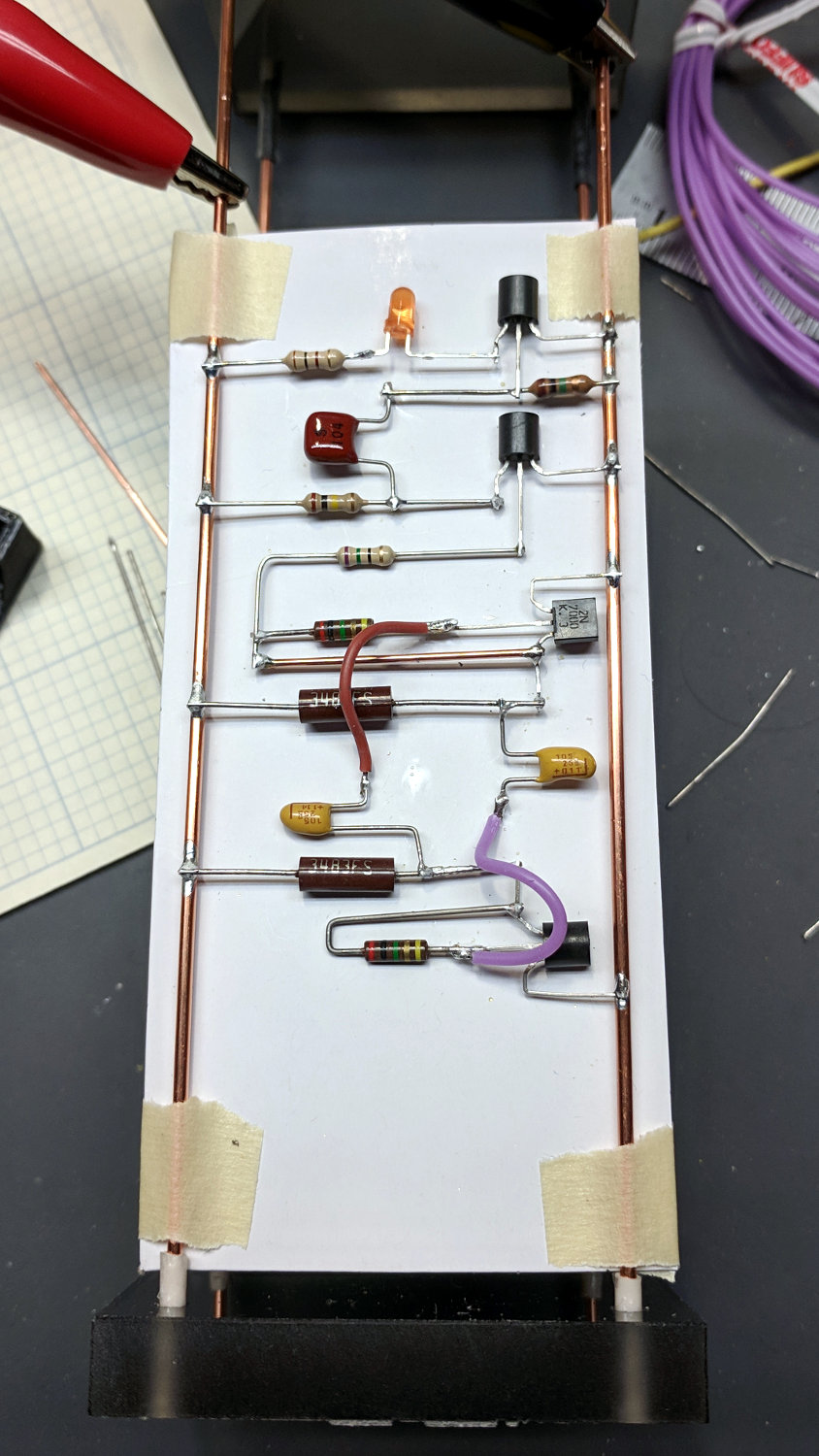
Taping a cardboard support under the soldering fixture helped hold all the parts in place:

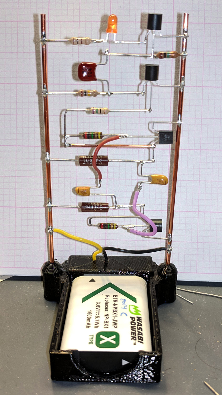
Astable – 2N7000 soldering The struts fit neatly into an NP-BX1 battery holder and the circuit began blinking merrily:
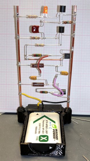
Astable – 2N7000 assembled My photography hand is weak …
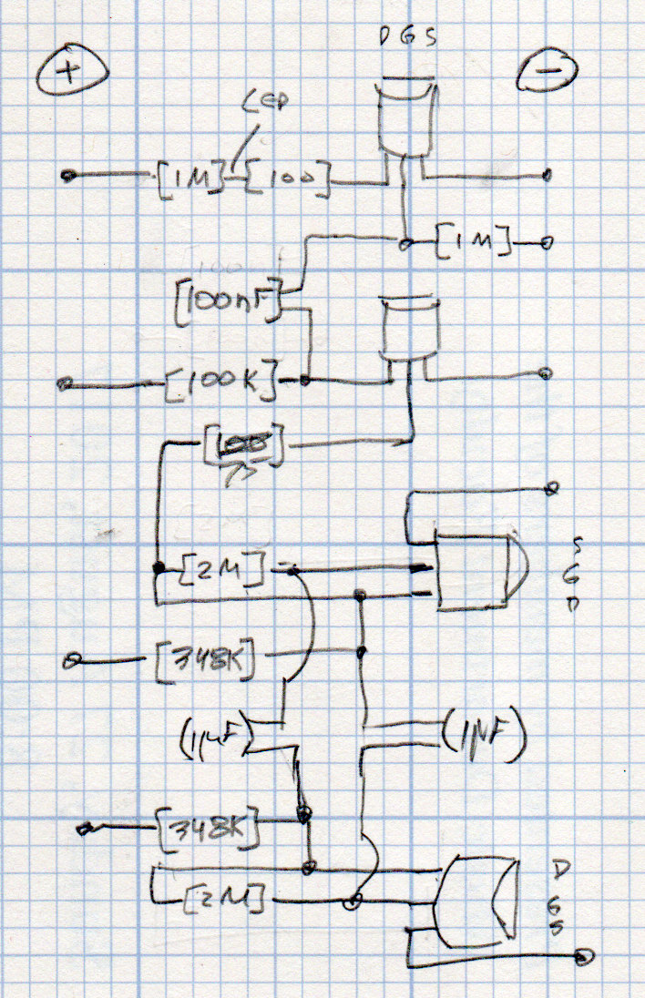
The circuit schematic / layout resembles this:
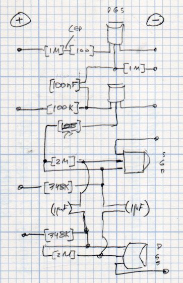
LED Schematic – MOSFET transistors The missing 1 MΩ resistor at the LED would serve as a physical support to tether the loose end of the 100 (-ish) Ω resistor, which desperately needed some stabilization under the LED spider.
The simulation says it should blink about every 4s:

Astable – 2N7000 buffered – true model The 2N7000 MOSFETs use a SPICE model from the
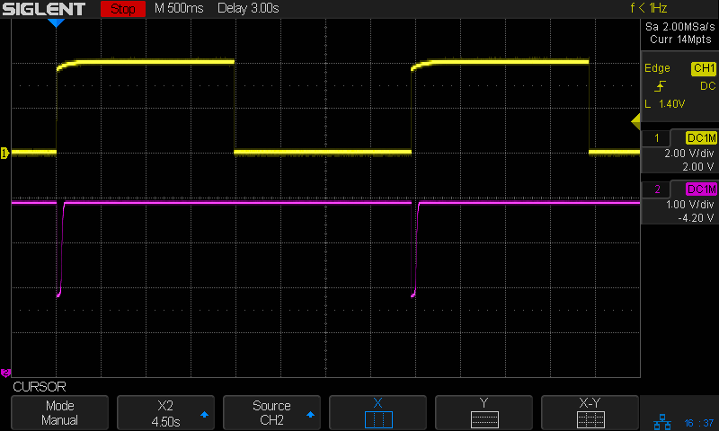
MotorolaON Semi downloads, although they behaved about the same way using the LTSpice 2N7002 model.It really does blink every 4s:

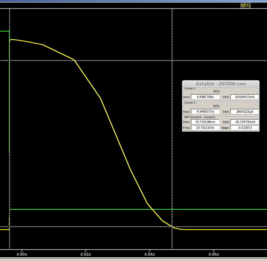
Astable – 2N7000 overview The LED pulse width should be about 50 ms:
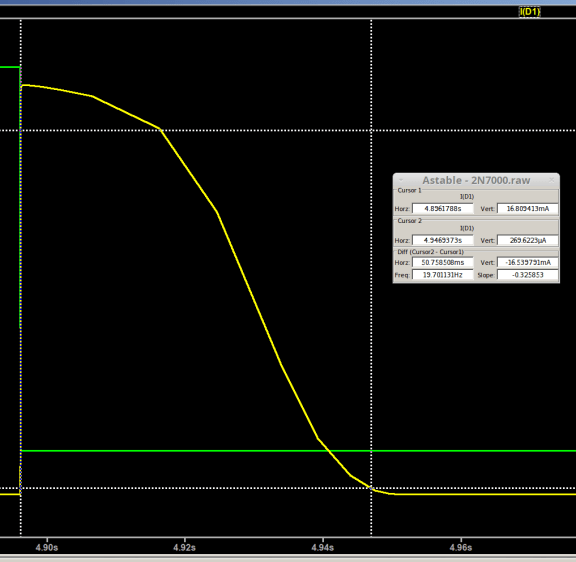
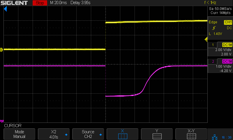
Astable – 2N7000 buffered – LED current – true model The voltage at the bottom of the ballast resistor is directly proportional to the LED current:
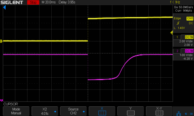
Astable – 2N7000 pulse detail So the pulse is actually 80-ish ms, which is Close Enough™ for my purposes.
The key advantage here is making both the astable’s period and the blink’s duration (roughly) proportional to the component values, so I can tweak them with some confidence the results will come out more-or-less right.
I love it when a plan comes together!

-
Subscribe
Subscribed
Have a WordPress.com account? Log in now.

