-
CNC 3018XL: Pilot V5RT Pen Holder
It turns out my all-time favorite Pilot Precise V5 Extra Fine stick pen also comes in a clicky-top retractable version:
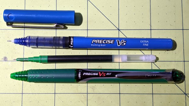
Pilot V5 and V5RT pens The cartridge is a nice 6 mm cylinder, eminently transformable into a plotter pen:
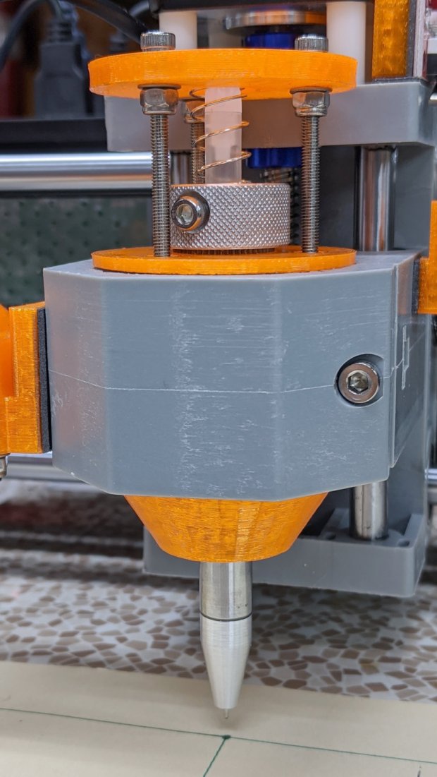
Pilot V5RT holder – installed A few minutes with a caliper provides key measurements for a snout surrounding the business end:

Pilot V5RT Pen Holder – snout dimension doodle The green letters & numbers give the nearest drill sizes. The “T” values along the bottom are the tailstock turns (at 1.5 mm/turn) required to poke the drills to the indicated depths, eyeballed when the body just enters the hole.
Having recently decomissioned the Thing-O-Matic and harvested its
organsparts, I have a vast collection of 3/8 inch = 9.52 mm shafts and matching bronze bushings: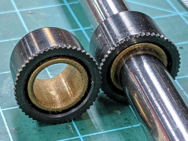
9.52 mm shaft and bushings Bronze bushings have low stiction, at least when they’re co-axial, and are much shorter than linear ball bearings.
I chopped off a 70 mm length of shaft and faced the raw end:
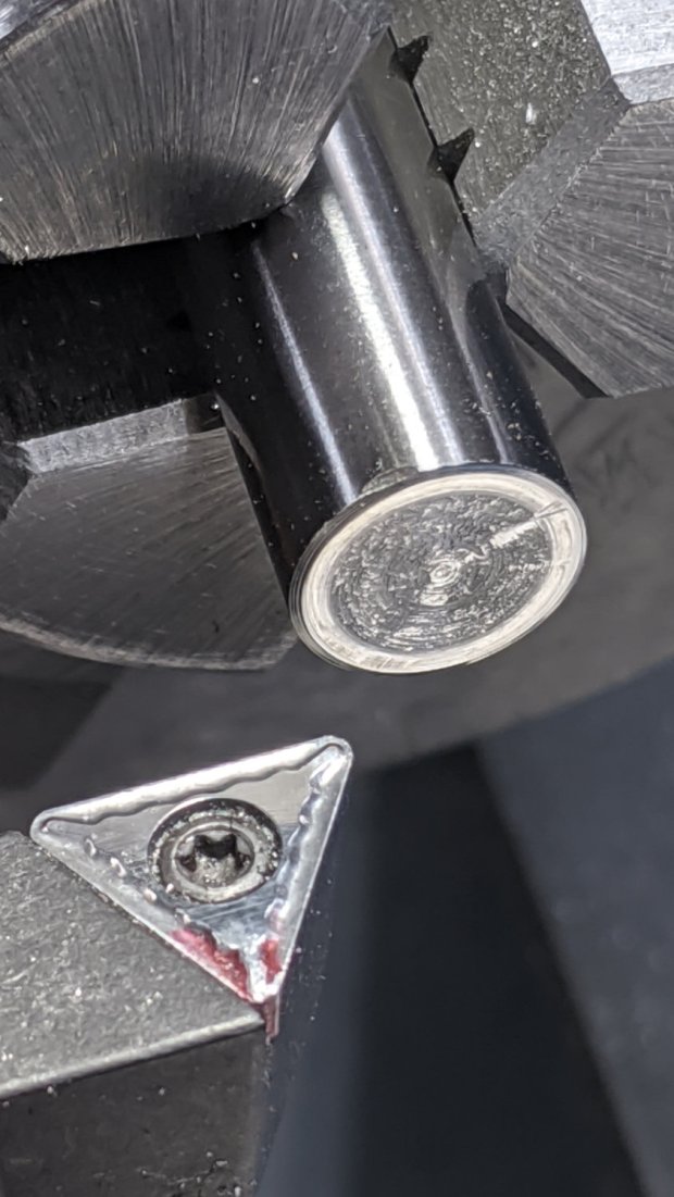
Pilot V5RT holder – facing shaft The other end had a maker’s logo, but I don’t recognize it:

Pilot V5RT holder – center drill I really wanted an 8 mm bore around the snout, but it just didn’t work out. The ring around the 7.5 mm counterbore shows where the larger drill just … stopped:

Pilot V5RT holder – drilled shaft A trial fit with the pen cartridge:

Pilot V5RT holder – pen in shaft The top of the shaft gets a somewhat longer knurled ring for the 3 mm SHCS holding the cartridge in place:
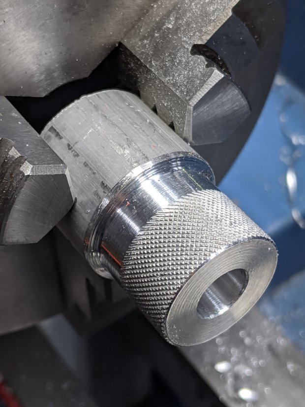
Pilot V5RT holder – knurling pen clamp The screw bears on a split collar turned and drilled from a Delrin rod:

Pilot V5RT holder – drilling Delrin clamp The “split” came from a simple saw cut across one side and I milled a flat spot in the knurling to seat the screw. As usual, the knurled ring got epoxied to the shaft.
The snout started as a 3/8 inch aluminum rod, drilled as shown in the sketch, with a (scant) 7.5 mm section to fit the shaft. The carbide insert left a nicely rounded shoulder that required trimming to fit snugly into the shaft:
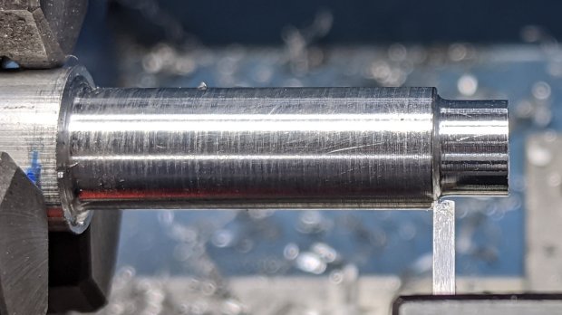
Pilot V5RT holder – shaping snout seat The compound can handle the shallow angle required to shape the snout:

Pilot V5RT holder – tapering snout A trial fit showed the snout was a bit too long for comfort:

Pilot V5RT holder – snout test fit Making something shorter doesn’t pose much of a challenge:
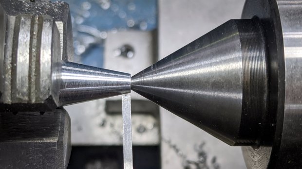
Pilot V5RT holder – trimming snout Another trial fit shows it’s spot on:

Pilot V5RT holder – shaft snout pen test fit The critical part is having the snout support the plastic around the pen tip to prevent wobbulation.
Epoxy the whole thing together, add a suitable spring, tighten the screws & nuts for the reaction plate, and it’s all good. I write with about 50 g of force for these pens, so a light preload seemed in order:
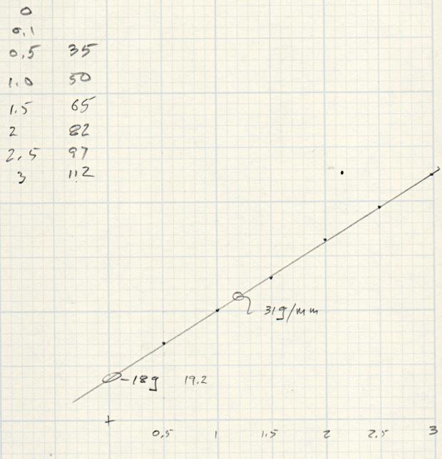
Pilot V5RT Pen Holder – initial downforce measurement If I’d weighed the full-up shaft + snout + collar + cartridge, I’d know if the Y intercept matches that weight. It seems a little lighter, but I’m not taking the thing apart to find out.
The first version of the 3D printed holder (shown above) is a straightforward modification of the LM12UU diamond drag bit holder, but, after building enough of these things, I realized the circular reaction plate should be triangular to get more clearance in front of the Z-axis stepper motor when installing & removing the holder:

Pilot V5RT Pen Holder – solid model – show view It also has a recess for the serrated top of the bearing, to prevent the knurled collar from clicking annoyingly as the Z-axis rises at the end of each stroke.
Now, to see how well it draws!
The OpenSCAD source code as a GitHub Gist:
This file contains hidden or bidirectional Unicode text that may be interpreted or compiled differently than what appears below. To review, open the file in an editor that reveals hidden Unicode characters. Learn more about bidirectional Unicode characters// Diamond Scribe in linear bearings for CNC3018 // Ed Nisley KE4ZNU – 2019-08-9 Layout = "Build"; // [Build, Show, Base, Mount, Plate] /* [Hidden] */ ThreadThick = 0.25; // [0.20, 0.25] ThreadWidth = 0.40; // [0.40, 0.40] /* [Hidden] */ Protrusion = 0.1; // [0.01, 0.1] HoleWindage = 0.2; inch = 25.4; function IntegerMultiple(Size,Unit) = Unit * ceil(Size / Unit); ID = 0; OD = 1; LENGTH = 2; //- Adjust hole diameter to make the size come out right module PolyCyl(Dia,Height,ForceSides=0) { // based on nophead's polyholes Sides = (ForceSides != 0) ? ForceSides : (ceil(Dia) + 2); FixDia = Dia / cos(180/Sides); cylinder(r=(FixDia + HoleWindage)/2,h=Height,$fn=Sides); } //- Dimensions PenOD = 6.1; // pen refill shaft, max OD Bearing = [(3.0/8.0)*inch,16.0,10.6]; // linear bearing body, ID = shaft diameter BearingFlange = [Bearing[OD],17.2,1.0]; // flange around end of bearing Spring = [8.5,9.5,15.5]; // compression spring around shaft, LENGTH = uncompressed SpringRecess = 4*ThreadThick; WallThick = 4.0; // minimum thickness / width Screw = [3.0,6.75,25.0]; // holding it all together, OD = washer Insert = [3.0,4.2,7.9]; // brass insert //Insert = [3.0,5.0,8.0]; //Insert = [4.0,6.0,10.0]; Clamp = [43.2,44.0,34.0]; // tool clamp ring, OD = clearance around top LipHeight = IntegerMultiple(2.0,ThreadThick); // above clamp for retaining BottomExtension = 15.0; // below clamp to reach workpiece MountOAL = LipHeight + Clamp[LENGTH] + BottomExtension; // total mount length echo(str("Mount OAL: ",MountOAL)); Plate = [PenOD + 4*ThreadWidth,Clamp[ID] – 0*2*WallThick,WallThick]; // spring reaction plate echo(str("Screw length: ",Spring[LENGTH] + Plate[LENGTH] + Insert[LENGTH])); NumScrews = 3; ScrewBCD = Bearing[OD] + Insert[OD] + 2*WallThick; echo(str("Retainer max OD: ",ScrewBCD – Screw[OD])); NumSides = 9*4; // cylinder facets (multiple of 3 for lathe trimming) // Basic mount shape module CNC3018Base() { translate([0,0,MountOAL – LipHeight]) cylinder(d=Clamp[OD],h=LipHeight,$fn=NumSides); translate([0,0,MountOAL – LipHeight – Clamp[LENGTH] – Protrusion]) cylinder(d=Clamp[ID],h=(Clamp[LENGTH] + 2*Protrusion),$fn=NumSides); cylinder(d1=Bearing[OD] + 2*WallThick,d2=Clamp[ID],h=BottomExtension + Protrusion,$fn=NumSides); } // Mount with holes & c module Mount() { difference() { CNC3018Base(); translate([0,0,-Protrusion]) // bearing PolyCyl(Bearing[OD],2*MountOAL,NumSides); translate([0,0,-Protrusion]) // bearing flanges PolyCyl(BearingFlange[OD],BearingFlange[LENGTH] + Protrusion,NumSides); translate([0,0,MountOAL – 1.5*BearingFlange[LENGTH]]) // sink into surface PolyCyl(BearingFlange[OD],2*BearingFlange[LENGTH],NumSides); for (i=[0:NumScrews – 1]) // clamp screws rotate(i*360/NumScrews) translate([ScrewBCD/2,0,MountOAL – Clamp[LENGTH]]) rotate(180/8) PolyCyl(Insert[OD],Clamp[LENGTH] + Protrusion,8); } } module SpringPlate() { difference() { hull() for (i=[0:NumScrews – 1]) rotate(i*360/NumScrews) translate([ScrewBCD/2,0,0]) cylinder(d=Screw[OD] + 4*ThreadWidth,h=Plate[LENGTH],$fn=24); translate([0,0,-Protrusion]) PolyCyl(Plate[ID],2*MountOAL,NumSides); translate([0,0,Plate[LENGTH] – SpringRecess]) // spring retainer PolyCyl(Spring[OD] + 4*ThreadWidth,SpringRecess + Protrusion,NumSides); for (i=[0:NumScrews – 1]) // clamp screws rotate(i*360/NumScrews) translate([ScrewBCD/2,0,-Protrusion]) rotate(180/8) PolyCyl(Screw[ID],2*MountOAL,8); } } //—– // Build it if (Layout == "Base") CNC3018Base(); if (Layout == "Mount") Mount(); if (Layout == "Plate") SpringPlate(); if (Layout == "Show") { Mount(); translate([0,0,MountOAL + Plate[LENGTH] + Spring[LENGTH]]) rotate([180,0,0]) SpringPlate(); } if (Layout == "Build") { translate([0,-0.75*Clamp[OD],MountOAL]) rotate([180,0,0]) Mount(); translate([0,0.75*Plate[OD],0]) SpringPlate(); }
-
Subscribe
Subscribed
Have a WordPress.com account? Log in now.

