-
CNC 3018XL: Adding Run-Hold Switches
Although the bCNC GUI has conspicuous Run / Hold buttons, it’s easier to poke a physical switch when you really really need a pause in the action or have finished a (manual) tool change. Rather than the separate button box I built for the frameless MPCNC, I designed a chunky switch holder for the CNC 3018XL’s gantry plate:
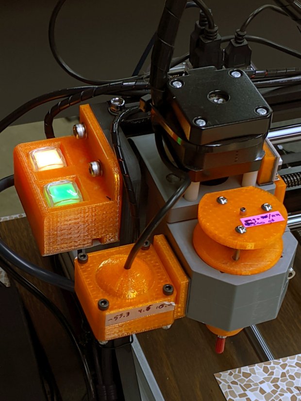
CNC 3018-Pro – Run Hold Switches – installed The original 15 mm screws were just slightly too short, so those are 20 mm stainless SHCS with washers.
The switches come from a long-ago surplus deal and have internal green and red LEDs. Their transparent cap shows what might be white plastic underneath:
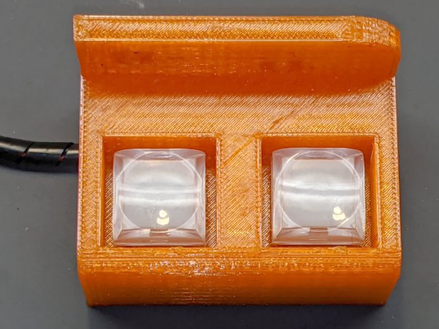
CNC 3018-Pro – Run Hold Switches – top unlit I think you could pry the cap off and tuck a printed legend inside, but appropriate coloration should suffice:

CNC 3018-Pro – Run Hold Switches – lit Making yellow from red and green LEDs always seems like magic; in these buttons, red + green produces a creamy white. Separately, the light looks like what you get from red & green LEDs.
The solid model shows off the recesses around the LED caps, making their tops flush with the surface to prevent inadvertent pokery:

Run Hold Switch Mount – Slic3r The smaller square holes through the block may require a bit of filing, particularly in the slightly rounded corners common to 3D printing, to get a firm press fit on the switch body. The model now has slightly larger holes which may require a dab of epoxy.
A multi-pack of RepRap-style printer wiring produced the cable, intended for a stepper motor and complete with a 4-pin Dupont socket housing installed on one end. I chopped the housing down to three pins, tucked the fourth wire into a single-pin housing, and plugged them into the CAMtool V3.3 board:
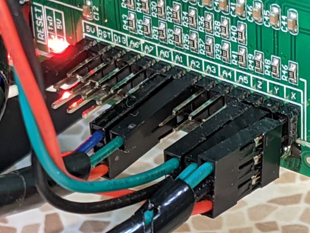
CNC 3018-Pro – Run Hold Switches – CAMtool V3.3 header The CAMtool schematic matches the default GRBL pinout, which comes as no surprise:

CAMtool schematic – Start Hold pinout The color code, such as it is:
- Black = common
- Red = +5 V
- Green = Run / Start (to match the LED)
- Blue = Hold (because it’s the only color left)
The cable goes into 4 mm spiral wrap for protection & neatness, with the end hot-melt glued into the block:

CNC 3018-Pro – Run Hold Switches – bottom The model now includes the wiring channel between the two switches, which is so obviously necessary I can’t imagine why I didn’t include it. The recess on the top edge clears the leadscrew sticking slightly out of the gantry plate.
The LEDs require ballast resistors: 120 Ω for red and 100 Ω for green, producing about 15 mA in each LED. Those are 1/8 W film resistors; I briefly considered SMD resistors, but came to my senses just in time.
A layer of black duct tape finishes the bottom sufficiently for my simple needs.
Note: the CAMtool board doesn’t have enough +5 V pins, so add a row of +5 V pins just below the standard header. If you’ve been following along, you needed them when you installed the home switches:

3018 CNC CAMTool – Endstop power mod A doodle giving relevant dimensions and layouts:

Run Hold Switch Mount – Layout Doodles I originally planned to mount the switches on the other gantry plate and sketched them accordingly, but (fortunately) realized the stepper motor was in the way before actually printing anything.
The OpenSCAD source code as a GitHub Gist:
This file contains hidden or bidirectional Unicode text that may be interpreted or compiled differently than what appears below. To review, open the file in an editor that reveals hidden Unicode characters. Learn more about bidirectional Unicode characters// CNC 3018-Pro Run-Hold Switches // Ed Nisley – KE4ZNU – 2020-01 Layout = "Build"; // [Show,Build,ProjectionX,ProjectionY,ProjectionZ,Block] /* [Hidden] */ ThreadThick = 0.25; ThreadWidth = 0.40; HoleWindage = 0.2; Protrusion = 0.1; // make holes end cleanly function IntegerMultiple(Size,Unit) = Unit * ceil(Size / Unit); ID = 0; OD = 1; LENGTH = 2; inch = 25.4; //———————- // Dimensions RodScrewOffset = [22,0,-14.5]; // X=left edge, Y=dummy, Z=from top edge BeamScrewOffset = [50,0,-10]; LeadScrewOffset = [RodScrewOffset.x,0,-45]; // may be off the bottom; include anyway LeadScrew = [8.0,10.0,5.0]; // ID=actual, OD=clearance, LENGTH=stick-out Screw = [5.0,10.0,6.0]; // M5 SHCS, OD=washer, LENGTH=washer+head ScrewSides = 8; // hole shape WallThick = 3.0; // minimum wall thickness FlangeThick = 5.0; // flange thickness Switch = [15.0 + 2*HoleWindage,15.0 + 2*HoleWindage,12.5]; // switch body SwitchCap = [17.5,17.5,12.0]; // … pushbutton SwitchClear = SwitchCap + [2*2.0,2*2.0,Screw[OD]/(2*cos(180/ScrewSides))]; SwitchContacts = 5.0; // contacts below switch SwitchBase = SwitchContacts + Switch.z; // bottom to base of switch MountOffset = abs(RodScrewOffset.z) + SwitchClear.z; // top of switch mounting plate FrameWidth = 60.0; // CNC 3018-Pro upright FrameRadius = 10.0; // … front corner rounding CornerRadius = 5.0; // pretty part rounding CornerSquare = 10; // dummy for square corner MountOAL = [FrameWidth, // covers machine frame 2*FlangeThick + 2*Screw[LENGTH] + SwitchClear.y, // clear screw heads MountOffset + Switch.z + SwitchContacts ]; echo(str("MountOAL: ",MountOAL)); SwitchOC = [MountOAL.x/2,FlangeThick + 2*Screw[LENGTH] + SwitchClear.y/2,0]; CableOD = 5.0; NumSides = 2*3*4; Gap = 2.0; // between build layout parts //———————- // Useful routines module PolyCyl(Dia,Height,ForceSides=0) { // based on nophead's polyholes Sides = (ForceSides != 0) ? ForceSides : (ceil(Dia) + 2); FixDia = Dia / cos(180/Sides); cylinder(r=(FixDia + HoleWindage)/2, h=Height, $fn=Sides); } // Projections for intersections module ProjectionX() { sr = CornerSquare/2; rotate([0,90,0]) rotate([0,0,90]) linear_extrude(height=FrameWidth,convexity=3) // mirror([1,0]) // mount on motor side of gantry union() { translate([0,-MountOAL.z]) square([FlangeThick,MountOAL.z]); hull() { translate([MountOAL.y – CornerRadius,-MountOffset + SwitchCap.z – CornerRadius]) circle(r=CornerRadius,$fn=NumSides); translate([sr,-MountOffset + SwitchCap.z – sr]) square(CornerSquare,center=true); translate([sr,-MountOAL.z + sr]) square(CornerSquare,center=true); translate([MountOAL.y – sr,-MountOAL.z + sr]) square(CornerSquare,center=true); } } } module ProjectionY() { sr = CornerSquare/2; rotate([90,0,0]) translate([0,0,-FrameWidth]) difference() { linear_extrude(height=2*FrameWidth,convexity=3) hull() { translate([FrameRadius,-FrameRadius]) circle(r=FrameRadius,$fn=NumSides); translate([FrameWidth – sr,-sr]) square(CornerSquare,center=true); translate([sr,-MountOAL.z + sr]) square(CornerSquare,center=true); translate([MountOAL.x – sr,-MountOAL.z + sr]) square(CornerSquare,center=true); } translate([RodScrewOffset.x,RodScrewOffset.z,-Protrusion]) rotate(180/ScrewSides) PolyCyl(Screw[ID],2*(FrameWidth + Protrusion),ScrewSides); for (j=[-FlangeThick,FrameWidth + FlangeThick]) translate([RodScrewOffset.x,RodScrewOffset.z,j]) rotate(180/ScrewSides) PolyCyl(Screw[OD],FrameWidth,ScrewSides); translate([BeamScrewOffset.x,BeamScrewOffset.z,-Protrusion]) rotate(180/ScrewSides) PolyCyl(Screw[ID],2*(FrameWidth + Protrusion),ScrewSides); for (j=[-FlangeThick,FrameWidth + FlangeThick]) translate([BeamScrewOffset.x,BeamScrewOffset.z,j]) rotate(180/ScrewSides) PolyCyl(Screw[OD],FrameWidth,ScrewSides); translate([LeadScrewOffset.x,LeadScrewOffset.z,FrameWidth – LeadScrew[LENGTH]]) rotate(180/ScrewSides) PolyCyl(LeadScrew[OD],2*LeadScrew[LENGTH],ScrewSides); } } module ProjectionZ() { translate([0,0,-MountOAL.z]) // mirror([0,1]) // mount on motor side of gantry difference() { linear_extrude(height=MountOAL.z,convexity=3) difference() { square([MountOAL.x,MountOAL.y]); translate([SwitchOC.x/2,SwitchOC.y]) square([Switch.x,Switch.y],center=true); translate([3*SwitchOC.x/2,SwitchOC.y]) square([Switch.x,Switch.y],center=true); } for (i=[-1,1]) translate([i*SwitchOC.x/2 + MountOAL.x/2,SwitchOC.y,SwitchBase + MountOAL.z/2]) cube([SwitchClear.x,SwitchClear.y,MountOAL.z],center=true); translate([-Protrusion,SwitchOC.y – 2*CableOD – Switch.y/2,-Protrusion]) cube([MountOAL.x + 2*Protrusion,CableOD,CableOD + Protrusion],center=false); for (i=[-1,1]) translate([i*SwitchOC.x/2 + MountOAL.x/2,SwitchOC.y – SwitchCap.y/2,CableOD/2 – Protrusion]) cube([CableOD,SwitchClear.y/2,CableOD + Protrusion],center=true); translate([SwitchOC.x/2,SwitchOC.y – CableOD/2,-Protrusion]) cube([SwitchOC.x,CableOD,CableOD + Protrusion],center=false); } } module Block() { intersection() { ProjectionX(); ProjectionY(); ProjectionZ(); } } //- Build things if (Layout == "ProjectionX") ProjectionX(); if (Layout == "ProjectionY") ProjectionY(); if (Layout == "ProjectionZ") ProjectionZ(); if (Layout == "Block") Block(); if (Layout == "Show") { translate([-MountOAL.x/2,-MountOAL.y/2,MountOAL.z]) { Block(); translate([MountOAL.x/2 + SwitchOC.x/2,SwitchOC.y,SwitchCap.z/2 – MountOAL.z + SwitchBase + 0*Switch.z]) color("Yellow",0.75) cube(SwitchCap,center=true); translate([MountOAL.x/2 – SwitchOC.x/2,SwitchOC.y,SwitchCap.z/2 – MountOAL.z + SwitchBase + 0*Switch.z]) color("Green",0.75) cube(SwitchCap,center=true); } } if (Layout == "Build") translate([-MountOAL.x/2,-MountOAL.y/2,MountOAL.z]) Block(); It seems bCNC doesn’t update its “Restart Spindle” message after a tool change when you poke the green button (instead of the GUI button), but that’s definitely in the nature of fine tuning.
-
Subscribe
Subscribed
Have a WordPress.com account? Log in now.

