-
Anonymous White USB Charger: Teardown
Prompted by ericscott’s comment, I had to tear down the Anonymous White USB Charger to see what caused the bizarre current waveform when connected to the Arduino in a Glass Tile:

Tiles 2×2 – anon white charger – pulse detail – 50 mA-div Start by grabbing opposite corners in a small vise and gently cracking the solvent-bonded joint between the sections:
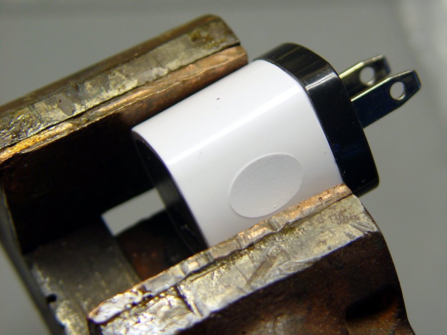
Anon white charger – case cracking Pull the base past the molded latches:
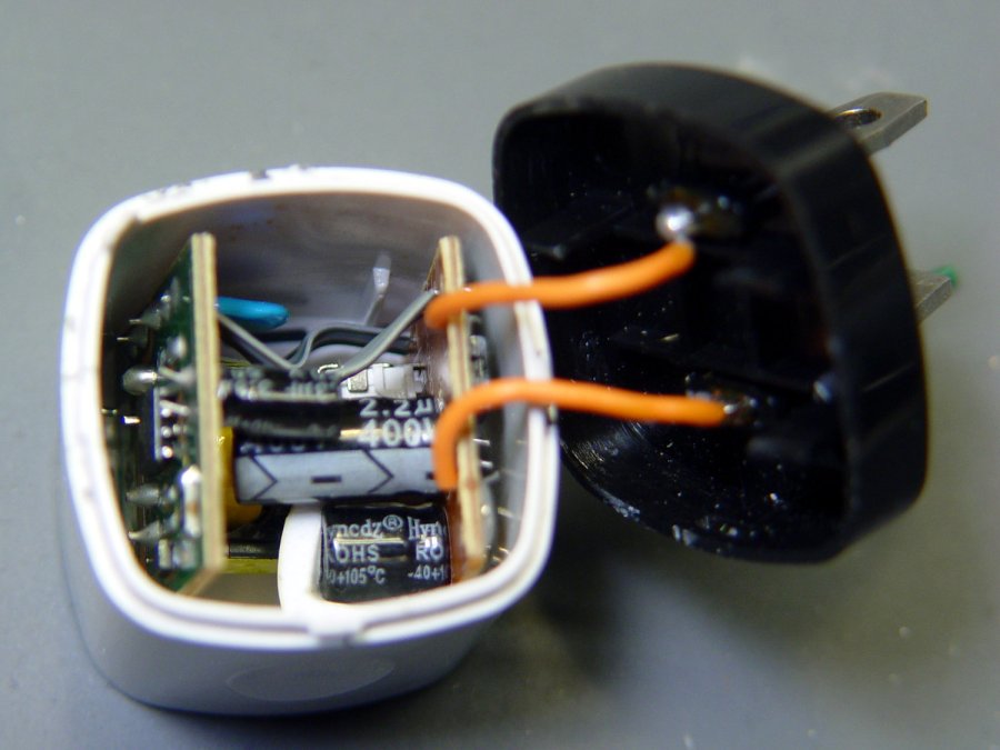
Anon white charger – case opened Behold: components!
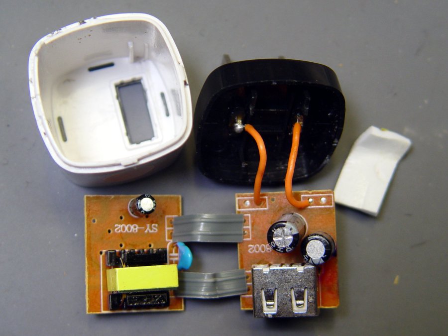
Anon white charger – PCB top On both sides of both PCBs!

Anon white charger – PCB bottom The top half of both boards, above the isolation cut, handles the line voltage and the lower half handles the 5 V USB output. You’ll note the absence of extra-cost parts like voltage feedback or ahem safety fuses.
The IC on the right half is labeled DP3773, which doesn’t seem to exist, but is surely similar to the LP3773 Low-Power Off-Line / PSR Controller.
Treating the whole regulator as a black box simplifies the schematic:

Anonymous white charger – schematic The cap bridging the two sides should be a Y capacitor, but it’s an ordinary 1 nF ceramic cap with a generous 1 kV rating. As far as I can tell, having it inject AC line noise directly into the +5 V side of the USB supply is just a bonus.
The base markings again:

Anonymous white charger – dataplate Whaddaya want for a buck, right?
-
Subscribe
Subscribed
Have a WordPress.com account? Log in now.

