-
Seedling Shelter Frame
Plant seedlings started in pots require some hardening off time outdoors before being transplanted. Veggie seedlings also require protection from critters regarding them as a buffet, so Mary covers them with a sheet of floating row cover, which must be both suspended over the plants to give them growing room and tucked under the tray to keep the bugs out. She asked for a frame to simplify the process:

Mesh Shelter Frame – assembled The solid model shows the structure with no regard for proportion:
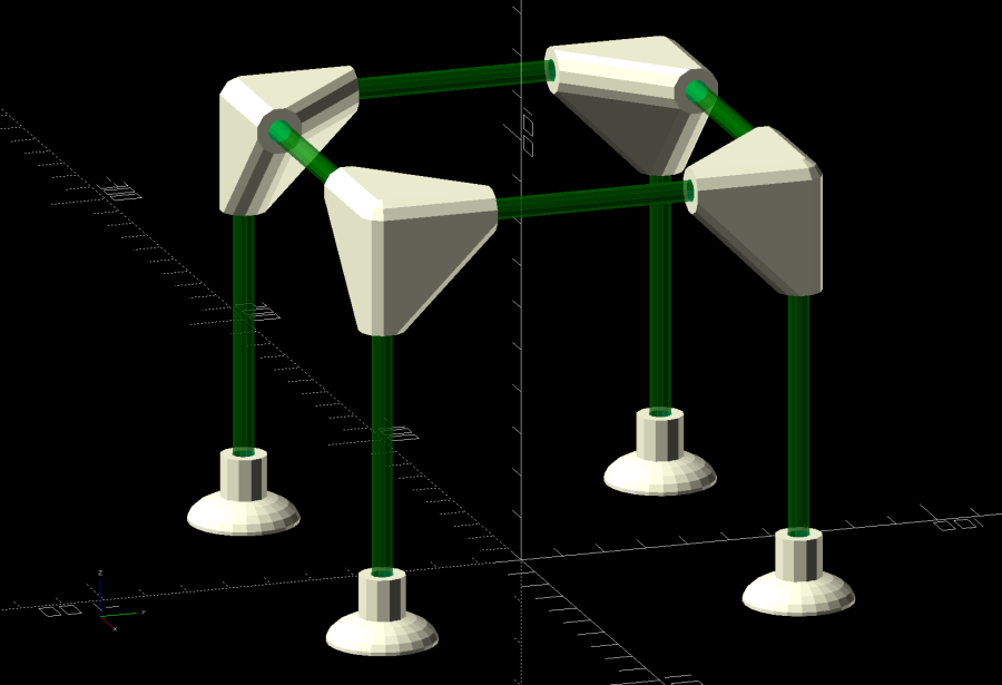
Mesh Shelter Frame – show view The 5 mm fiberglass rods come from our decommissioned six-passenger umbrella, cut to length in the Tiny Lathe™ by applying a Swiss Pattern knife file around the perimeter, over the ShopVac’s snout to catch the glass dust. I started with a pull saw (also over the vacuum) during the weekly Squidwrench v-meeting, whereupon Amber recommended either a Dremel slitting wheel or a file, so I mashed everything together and it worked wonderfully well, without producing any errant glass-fiber shards to impale my fingers.
The corners consist of three tubes stuck together at the origin:
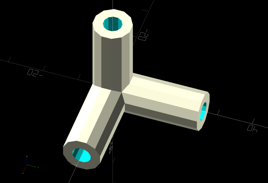
Mesh Shelter Frame – non-hulled corner model Shrink-wrapping them with a
hull()adds plenty of strength where it’s needed: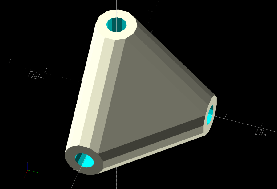
Mesh Shelter Frame – hulled corner model I decided putting the belly side (facing you in the picture) downward on the platform and the peak upward would distribute the distortion equally among the tubes and produce a nicely rounded outer surface for the mesh fabric:
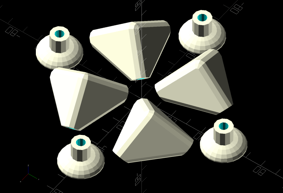
Mesh Shelter Frame – build layout Which led to some Wikipedia trawling to disturb the silt over my long-buried analytic geometry, plus some calculator work to help recall the process; back in the day I would have used a slipstick, but I was unwilling to go there. Although I could special-case this particular layout, the general method uses Euler’s Rotation Theorem, simplified because I need only one rotation.
Should you need concatenated rotations, you probably need quaternions, but, at this point, I don’t even remember forgetting quaternions.
Anyhow, the Euler rotation axis is the cross product of the [1,1,1] vector aimed through the middle of the corner’s belly with the [0,0,-1] target vector pointing downward toward the platform. The rotation amount is the
acos()of the dot product of those two vectors divided by the product of their norms. With vector and angle in hand, dropping them into OpenSCAD’s rotate() transformation does exactly what’s needed:rotate(acos((BaseVector*Nadir)/(norm(BaseVector)*norm(Nadir))), v=cross(BaseVector,Nadir)) // aim belly side downward Corner();Dang, I was so happy when that worked!
Because the corner model rotates around the origin where all three tube centerlines meet, the result puts the belly below the platform, pointed downward. The next step applies a translation to haul the belly upward:
translate([ArmOAL,0,    // raise base to just below platform level
           ArmOC/sqrt(3) + (ArmRadius/cos(180/SocketSides))*cos(atan(sqrt(3)/2)) + Finagle])
This happens in a loop positioning the four corners for printing, so the first
ArmOALas the X axis parameter translates the shape far enough to let four of them coexist around the origin, as shown above.The mess in the Z axis parameter has three terms:
- Raise the centerline of the ends of the tubes to Z=0
- Raise the rim of the tube to Z=0
- Add a wee bit to make the answer come out right
The 0.18 mm
Finagleconstant fixes things having to do with thehull()applied to miscellaneous leftover angled-circles-as-polygons approximations and leaves just a skin below the platform to be sheared off by a huge cube below Z=0, matching the corner bellies with the bottoms of the feet.Because the corners have awful overhangs, the results look a bit raggedy:

Mesh Shelter Frame – corner underside That’s after knocking off the high spots with a grubby sanding sponge and making a trial fit. They look somewhat less grotendous in person.
If we need another iteration, I’ll think hard about eliminating the overhangs by splitting the corner parallel to the belly, flipping the belly upward, and joining the pieces with a screw. What we have seems serviceable, though.
The OpenSCAD source code as a GitHub Gist:
This file contains hidden or bidirectional Unicode text that may be interpreted or compiled differently than what appears below. To review, open the file in an editor that reveals hidden Unicode characters. Learn more about bidirectional Unicode characters// Mesh Shelter Frame for outdoor sprouts // Ed Nisley KE4ZNU – July 2020 /* [Layout Options] */ Layout = "Show"; // [Build, Show, Corner, CornerSet, Base, BaseSet] //——- //- Extrusion parameters must match reality! // Print with 2 shells /* [Hidden] */ ThreadThick = 0.25; ThreadWidth = 0.40; HoleFinagle = 0.2; HoleFudge = 1.00; function HoleAdjust(Diameter) = HoleFudge*Diameter + HoleFinagle; Protrusion = 0.1; // make holes end cleanly function IntegerMultiple(Size,Unit) = Unit * ceil(Size / Unit); inch = 25.4; //——- // Dimensions RodOD = 5.0; SocketDepth = 3*RodOD; WallThick = 3.0; ArmOD = RodOD + 2*WallThick; ArmRadius = ArmOD / 2; SocketSides = 3*4; ArmOC = SocketDepth + ArmOD; // rod entry to corner centerline ArmOAL = ArmOC + ArmRadius; // total arm length to outer edge echo(str("ArmOC: ",ArmOC)); echo(str("ArmOAL: ",ArmOAL)); Nadir = [0,0,-1]; // vector toward print platform RodLength = 100; // just for show //——- module PolyCyl(Dia,Height,ForceSides=0) { // based on nophead's polyholes Sides = (ForceSides != 0) ? ForceSides : (ceil(Dia) + 2); FixDia = Dia / cos(180/Sides); cylinder(r=HoleAdjust(FixDia)/2,h=Height,$fn=Sides); } //——- BaseVector = [1,1,1]; // vector through middle of base surface module Corner() { difference() { hull() { scale([1/cos(180/SocketSides),1/cos(180/SocketSides),1]) rotate(180/SocketSides) sphere(d=ArmOD,$fn=SocketSides); rotate(180/SocketSides) cylinder(d=ArmOD,h=ArmOC,$fn=SocketSides); rotate([-90,0,0]) rotate(180/SocketSides) cylinder(d=ArmOD,h=ArmOC,$fn=SocketSides); rotate([0,90,0]) rotate(180/SocketSides) cylinder(d=ArmOD,h=ArmOC,$fn=SocketSides); } rotate(180/SocketSides) translate([0,0,ArmOD]) PolyCyl(RodOD,SocketDepth + Protrusion,SocketSides); rotate([-90,0,0]) rotate(180/SocketSides) translate([0,0,ArmOD]) PolyCyl(RodOD,SocketDepth + Protrusion,SocketSides); rotate([0,90,0]) rotate(180/SocketSides) translate([0,0,ArmOD]) PolyCyl(RodOD,SocketDepth + Protrusion,SocketSides); } } module CornerSet(s=RodLength) { translate([-s/2,-s/2,s]) mirror([0,0,1]) Corner(); translate([s/2,-s/2,s]) rotate([0,0,90]) mirror([0,0,1]) Corner(); translate([s/2,s/2,s]) rotate([0,0,180]) mirror([0,0,1]) Corner(); translate([-s/2,s/2,s]) rotate([0,0,-90]) mirror([0,0,1]) Corner(); } module Base() { difference() { union() { cylinder(d=ArmOD,h=ArmOAL/2,$fn=SocketSides); resize([0,0,ArmOC/2]) sphere(d=ArmOC,$fn=2*SocketSides); } translate([0,0,3*ThreadThick]) PolyCyl(RodOD,ArmOAL,SocketSides); translate([0,0,-SocketDepth]) // cut sphere below platform cube(2*SocketDepth,center=true); } } module BaseSet(s=RodLength) { for (i=[-1,1], j=[-1,1]) translate([i*s/2,j*s/2,0]) Base(); } //——- // Build it! if (Layout == "Corner") Corner(); if (Layout == "CornerSet") CornerSet(); if (Layout == "Base") Base(); if (Layout == "BaseSet") BaseSet(); if (Layout == "Show") { CornerSet(); for (i=[-1,1]) translate([i*RodLength/2,RodLength/2,RodLength]) rotate([90,0,0]) color("Green",0.5) cylinder(d=RodOD,h=RodLength,$fn=SocketSides); for (j=[-1,1]) translate([RodLength/2,j*RodLength/2,RodLength]) rotate([0,-90,0]) color("Green",0.5) cylinder(d=RodOD,h=RodLength,$fn=SocketSides); BaseSet(); for (i=[-1,1], j=[-1,1]) translate([i*RodLength/2,j*RodLength/2,0]) color("Green",0.5) cylinder(d=RodOD,h=RodLength,$fn=SocketSides); } if (Layout == "Build") { Finagle = 0.18; // hack for hull's angled round-to-polygon approximations, I think difference() { // slice sliver from base to sit flat on platform union() for (a=[45:90:360]) rotate(a) // distribute around origin translate([ArmOAL,0, // raise base to just below platform level ArmOC/sqrt(3) + (ArmRadius/cos(180/SocketSides))*cos(atan(sqrt(3)/2)) + Finagle]) rotate(17) // arbitrary rotation for tidy arrangement rotate(acos((BaseVector*Nadir)/(norm(BaseVector)*norm(Nadir))), v=cross(BaseVector,Nadir)) // aim belly side downward Corner(); translate([0,0,-ArmOD/2]) // slicing block below platform cube([6*ArmOAL,6*ArmOAL,ArmOD],center=true); } rotate(45) for (i=[-1,1], j=[-1,1]) translate([i*1.5*ArmOC,j*1.5*ArmOC,0]) Base(); }
-
Subscribe
Subscribed
Have a WordPress.com account? Log in now.

