-
Raspberry Pi Interrupts vs. Rotary Encoder
Thinking about using a rotary encoder to focus a Raspberry Pi lens led to a testbed:

RPi knob encoder test setup There’s not much to it, because the RPi can enable pullup resistors on its digital inputs, whereupon the encoder switches its code bits to common. The third oscilloscope probe to the rear syncs on a trigger output from my knob driver.
I started with the Encoder library from PyPi, but the setup code doesn’t enable the pullup resistors and the interrupt (well, it’s a callback) handler discards the previous encoder state before using it, so the thing can’t work. I kept the overall structure, gutted the code, and rebuilt it around a state table. The code appears at the bottom, but you won’t need it.
Here’s the problem, all in one image:
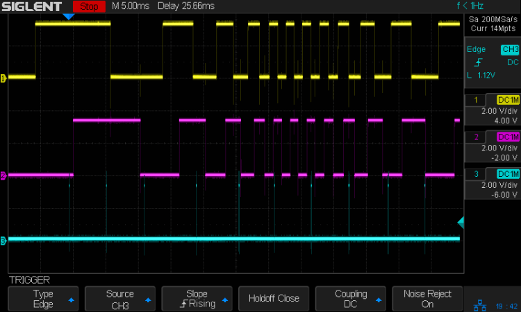
Knob Encoder – ABT – fast – overview The top two traces are the A and B encoder bits. The bottom trace is the trigger output from the interrupt handler, which goes high at the start of the handler and low at the end, with a negative blip in the middle when it detects a “no motion” situation: the encoder output hasn’t changed from the last time it was invoked.
Over on the left, where the knob is turning relatively slowly, the first two edges have an interrupt apiece. A detailed view shows them in action (the bottom half enlarge the non-shaded part of the top half):

Knob Encoder – ABT – fast – first IRQs Notice that each interrupt occurs about 5 ms after the edge causing it!
When the edges occur less than 5 ms apart, the driver can’t keep up. The next four edges produce only three interrupts:

Knob Encoder – ABT – fast – 4 edges 3 IRQ A closer look at the three interrupts shows all of them produced the “no motion” pulse, because they all sampled the same (incorrect) input bits:

Knob Encoder – ABT – fast – 4 edges 3 IRQ – detail In fact, no matter how many edges occur, you only get three interrupts:
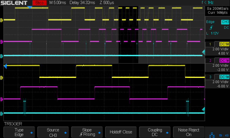
Knob Encoder – ABT – fast – 9 edges 3 IRQ The groups of interrupts never occur less than 5 ms apart, no matter how many edges they’ve missed. Casual searching suggests the Linux Completely Fair Scheduler has a minimum timeslice / thread runtime around 5 ms, so the encoder may be running at the fastest possible response for a non-real-time Raspberry Pi kernel, at least with a Python handler.
If. I. Turn. The. Knob. Slowly. Then. It. Works. Fine. But. That. Is. Not. Practical. For. My. Purposes.
Nor anybody else’s purposes, really, which leads me to think very few people have ever tried lashing a rotary encoder to a Raspberry Pi.
So, OK, I’ll go with
NearerandFartherfocusing buttons.The same casual searching suggested tweaking the Python thread’s priority / niceness could lock it to a different CPU core and, obviously, writing the knob handler in C / C++ / any other language would improve the situation, but IMO the result doesn’t justify the effort.
It’s worth noting that writing “portable code” involves more than just getting it to run on a different system with different hardware. Rotary encoder handlers are trivial on an Arduino or, as in this case, even an ARM-based Teensy, but “the same logic” doesn’t deliver the same results on an RPi.
My attempt at a Python encoder driver + simple test program as a GitHub Gist:
This file contains hidden or bidirectional Unicode text that may be interpreted or compiled differently than what appears below. To review, open the file in an editor that reveals hidden Unicode characters. Learn more about bidirectional Unicode characters# Rotary encoder test driver # Ed Nisley – KE4ZNU # Adapted from https://github.com/mivallion/Encoder # State table from https://github.com/PaulStoffregen/Encoder import RPi.GPIO as GPIO class Encoder(object): def __init__(self, A, B, T=None, Delay=None): GPIO.setmode(GPIO.BCM) self.T = T if T is not None: GPIO.setup(T, GPIO.OUT) GPIO.output(T,0) GPIO.setup(A, GPIO.IN, pull_up_down=GPIO.PUD_UP) GPIO.setup(B, GPIO.IN, pull_up_down=GPIO.PUD_UP) self.delay = Delay self.A = A self.B = B self.pos = 0 self.state = (GPIO.input(B) << 1) | GPIO.input(A) self.edges = (0,1,-1,2,-1,0,-2,1,1,-2,0,-1,2,-1,1,0) if self.delay is not None: GPIO.add_event_detect(A, GPIO.BOTH, callback=self.__update, bouncetime=self.delay) GPIO.add_event_detect(B, GPIO.BOTH, callback=self.__update, bouncetime=self.delay) else: GPIO.add_event_detect(A, GPIO.BOTH, callback=self.__update) GPIO.add_event_detect(B, GPIO.BOTH, callback=self.__update) def __update(self, channel): if self.T is not None: GPIO.output(self.T,1) # flag entry state = (self.state & 0b0011) \ | (GPIO.input(self.B) << 3) \ | (GPIO.input(self.A) << 2) gflag = '' if self.edges[state] else ' – glitch' if (self.T is not None) and not self.edges[state]: # flag no-motion glitch GPIO.output(self.T,0) GPIO.output(self.T,1) self.pos += self.edges[state] self.state = state >> 2 # print(' {} – state: {:04b} pos: {}{}'.format(channel,state,self.pos,gflag)) if self.T is not None: GPIO.output(self.T,0) # flag exit def read(self): return self.pos def read_reset(self): rv = self.pos self.pos = 0 return rv def write(self,pos): self.pos = pos if __name__ == "__main__": import encoder import time from gpiozero import Button btn = Button(26) enc = encoder.Encoder(20, 21,T=16) prev = enc.read() while not btn.is_held : now = enc.read() if now != prev: print('{:+4d}'.format(now)) prev = now
-
Subscribe
Subscribed
Have a WordPress.com account? Log in now.

