-
3D Printed Smashed Glass Coasters: Fragment Path Offsets, Simplified Version
Rather than use Inkscape or LightBurn to generate all the offsets required to make a solid model, it’s easier to let OpenSCAD handle it:
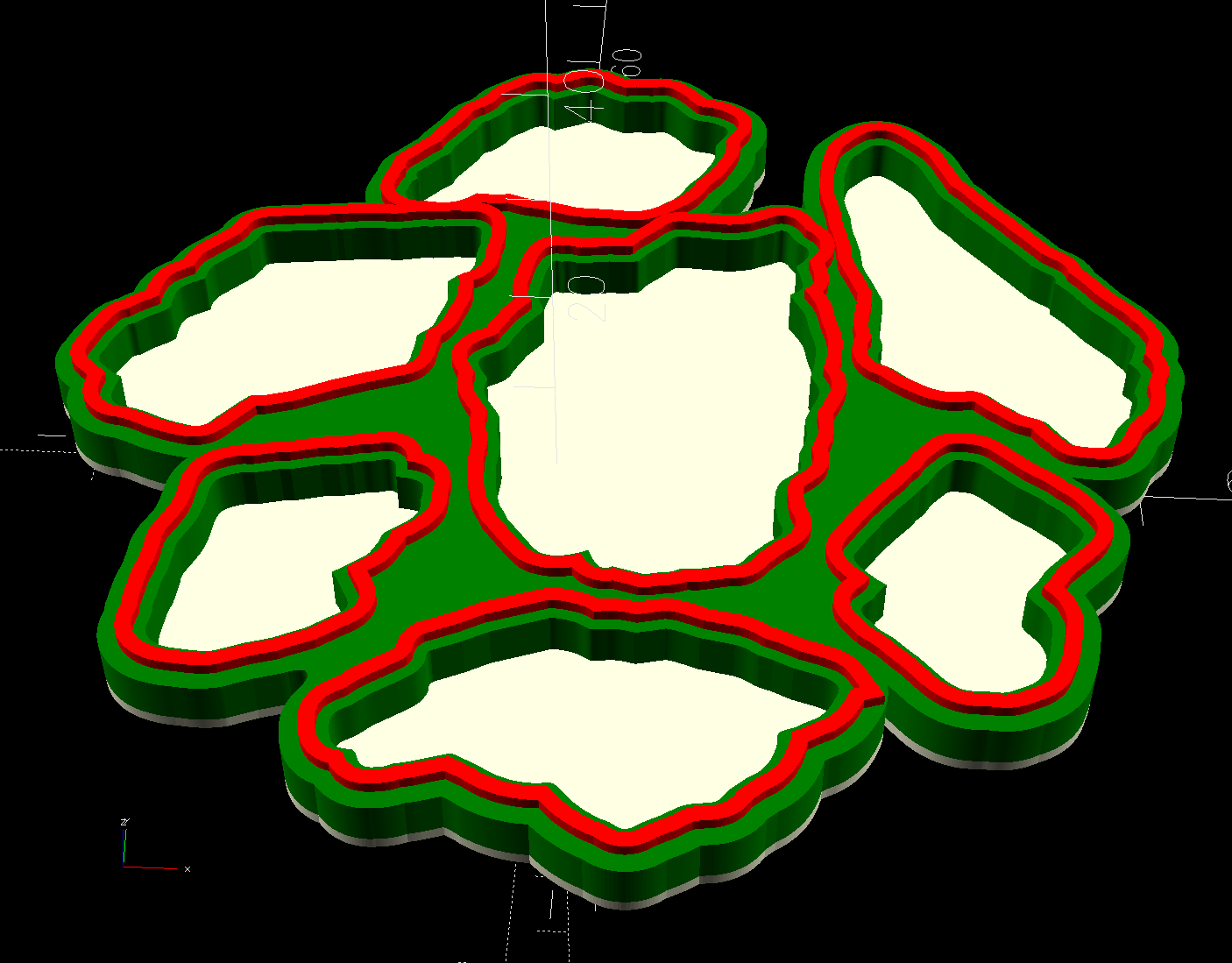
Printed Coaster Layout – 100 mm Set G – solid model The overall process:
- Pick some interesting fragments
- Scan to get an image
- Mark the fragments in GIMP
- Create a suitable circumcircle in LightBurn
- Use a nesting program like Deepnest to create a nice layout of the fragments within the circle
- Create the perimeter path as an offset around all the fragments in LightBurn
Because the fragments have irregular shapes and spacing, creating the perimeter path may also produce small snippets of orphaned geometry which must be manually selected and deleted. I also edit the path to remove very narrow channels between adjacent fragments.
Which is why you can’t generate that path automatically:
Printed Coaster Layout – 100 mm Set G – LightBurn perimeter geometry Because LightBurn doesn’t have the ability to name the various paths, the next step requires Inkscape. After importing the LightBurn paths saved as an SVG, group all the fragments and name the group
Fragments, then name the perimeter pathPerimeter: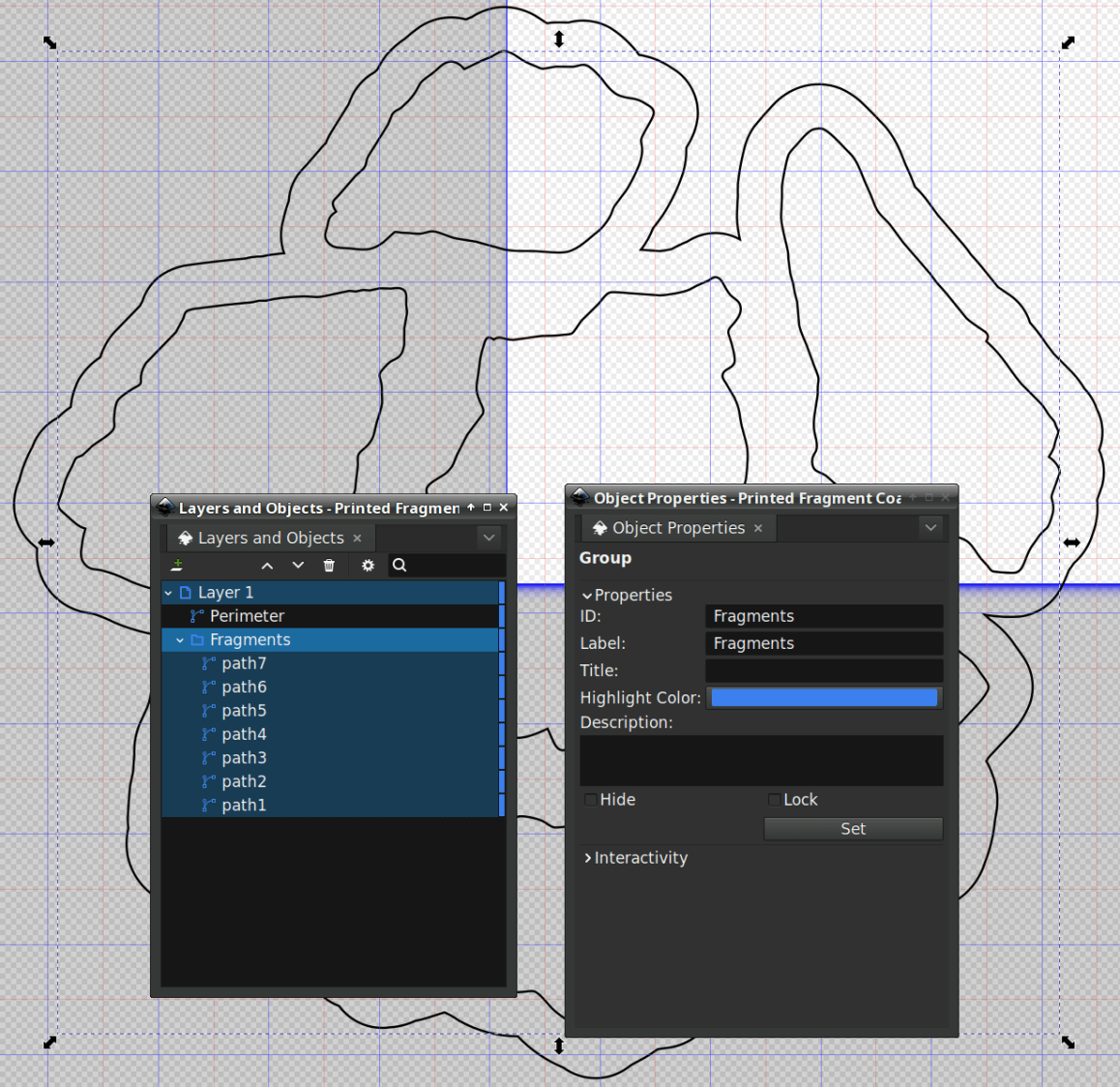
Printed Coaster Layout – 100 mm Set G – Inkscape layer and IDs Inkscape still crashes unpredictably while doing what seems to be a simple process, which may be due to the tremendous number of points in the hand-traced fragment outlines. Unfortunately, simplifying the curves in either LightBurn or Inkscape tends to round off the extreme points and increases the likelihood of the fragment not fitting into its recess.
OpenSCAD generates all the other features in the solid model with paths plucked from that file:
include <BOSL2/std.scad>

fn = "Printed Fragment Coaster - 100 mm Set G - Inkscape paths.svg";

FragmentThick = 3.8;

BaseThick = 1.0;
RimHeight = 1.0;

union() {

  linear_extrude(h=BaseThick)
    import(fn,id="Perimeter");

   color("Green")
  up(BaseThick)
    linear_extrude(h=FragmentThick)
      difference() {
        import(fn,id="Perimeter");
        offset(delta=0.2)
          import(fn,id="Fragments");
      }

  color("Red")
  up(BaseThick)
    linear_extrude(h=FragmentThick + RimHeight)
      difference() {
        offset(delta=2.5)
          import(fn,id="Fragments");
        offset(delta=1.2)
          import(fn,id="Fragments");
      }


}
The
Perimeterpath defines the overall shape of the coaster as a 1.0 mm thick slab, visible as the white-ish line around the edge and at the bottom of all the fragment recesses.Atop that, the green shape is the same
Perimetershape, with theFragmentshapes removed after theoffset()operation enlarges them by 0.2 mm to ensure enough clearance.Finally, the red walls containing the epoxy above each fragment are 1.3 mm wide, the difference of the two
offset()operations applied to theFragments.Because the outer edge of the wall is 2.5 mm away from the edge of its fragment:
- The
Perimeterpath must be offset at least 2.5 mm from theFragmentsin LightBurn. I used 4.0 mm to produce a small lip around the outside edge of the coaster. - The fragment shapes must be placed at least 5.0 mm apart to prevent the walls from overlapping. I set Deepnest to exactly 5.0 mm spacing, but you can see a few places where the fragments come too close together. I think this happens due to an approximation
deepnestuses while rotating the paths, but it may be better to manually adjust the errant fragments than increase the average space.
While this still requires manually tracing the glass fragments and fiddling a bit with Inkscape, the overall process isn’t nearly as burdensome as getting all the offsets correct every time.
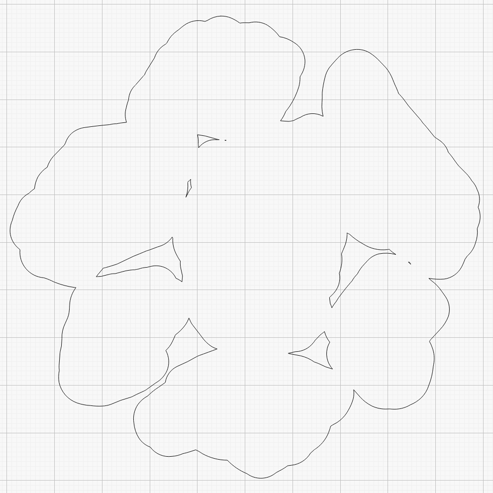
However, some oddities remain. OpenSCAD produced this result during the first pass through the process for this coaster:
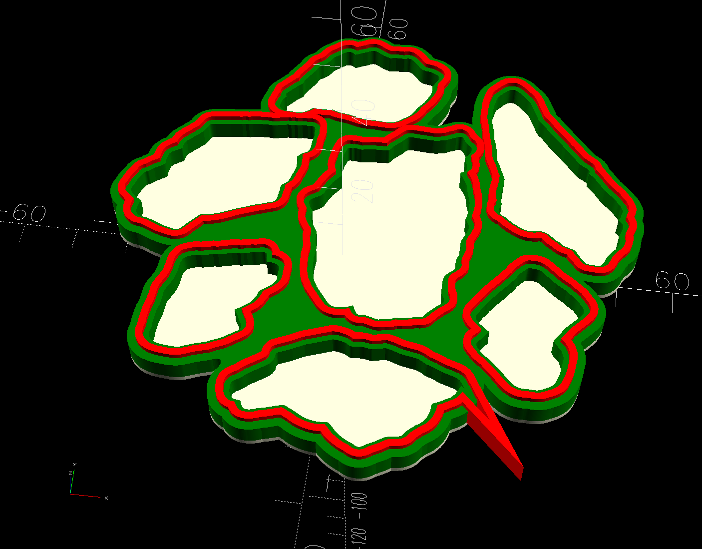
Printed Coaster Layout – 100 mm Set G – spurious point As far as I can tell, the spurious point came from a numeric effect, because telling Inkscape to store only five decimal places in the SVG file reduced the spike to the small bump seen in the first picture. I cannot replicate that effect using the same files and have no explanation.
-
Subscribe
Subscribed
Already have a WordPress.com account? Log in now.
