-
Tour Easy Rear Running Light: Circuit Support Plate
Building the circuit support plate for the amber front running light was entirely too fiddly:
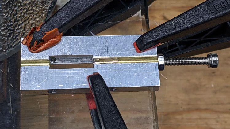
1 W LED Running Light – baseplate dry assembly This was definitely easier:
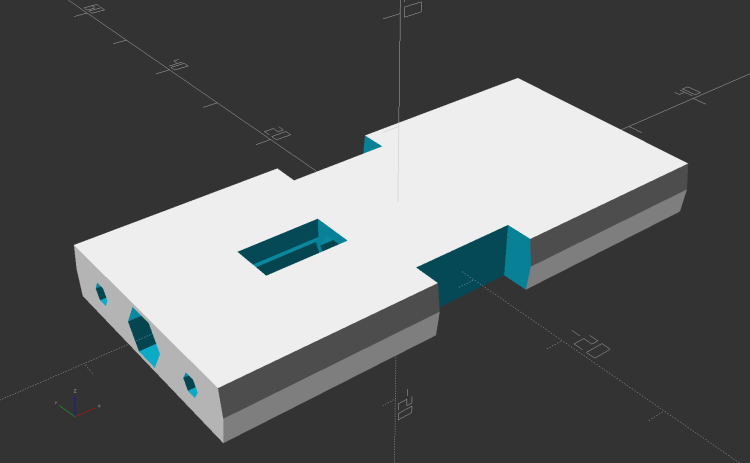
Running Light Circuit Plate – solid model Two pins fit in the small holes to align it with the LED heatsink, with an M3 stud and brass insert holding it in place:
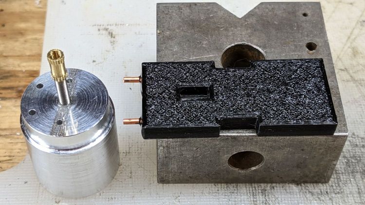
Tour Easy Rear Running Light – circuit plate attachment The rectangular hole around the insert let me glop urethane adhesive over it to lock it into the plate, with more goop on the screw and pins to unify heatsink and plate.
The LED wires now emerge from the heatsink on the same side of the plate, simplifying the connections to the MP1584 regulator and current-sense resistor:
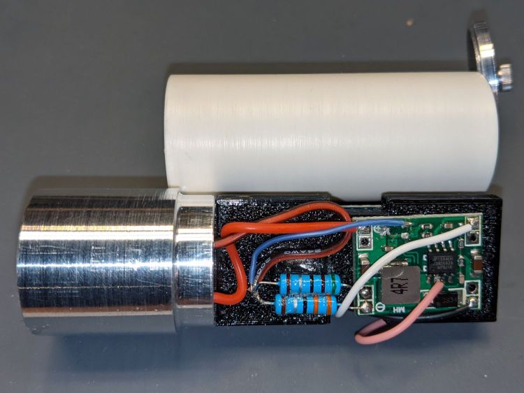
Tour Easy Rear Running Light – regulator wiring The paralleled 5.1 Ω and 3.3 Ω resistors form a 2.0 Ω resistor setting the LED current to 400 mA = 1 W at 2.6 V forward drop. They’re 1 W resistors dissipating a total of 320 mW and get barely warm.
The resistors and wires are stuck in place with clear adhesive, so things shouldn’t rattle around too much.
The OpenSCAD source code as a GitHub Gist:
This file contains hidden or bidirectional Unicode text that may be interpreted or compiled differently than what appears below. To review, open the file in an editor that reveals hidden Unicode characters. Learn more about bidirectional Unicode characters// Circuit plate for Tour Easy running lights // Ed Nisley – KE4ZNU – 2021-09 /* [Hidden] */ ThreadThick = 0.25; ThreadWidth = 0.40; HoleWindage = 0.2; Protrusion = 0.1; // make holes end cleanly function IntegerMultiple(Size,Unit) = Unit * ceil(Size / Unit); ID = 0; OD = 1; LENGTH = 2; inch = 25.4; //———————- // Dimensions // Light case along X axis LightID = 23.0; WallThick = 2.0; Screw = [3.0,6.8,4.0]; // M3 OD=washer, length=nut + washers Insert = [3.0,4.2,8.0]; // splined brass insert, minus splines InsertOffset = 10.0; // insert from heatsink end PinOD = 1.6; // alignment pins PinOC = 14.0; PinDepth = 5.0; Plate = [50.0,LightID,Insert[OD] + 4*ThreadThick]; // overall plate size WirePort = [10.0,3.0,2*Plate.z]; NumSides = 2*3*4; //———————- // Useful routines module PolyCyl(Dia,Height,ForceSides=0) { // based on nophead's polyholes Sides = (ForceSides != 0) ? ForceSides : (ceil(Dia) + 2); FixDia = Dia / cos(180/Sides); cylinder(r=(FixDia + HoleWindage)/2, h=Height, $fn=Sides); } // Circuit plate module Plate() { difference() { intersection() { cube(Plate,center=true); rotate([0,90,0]) cylinder(d=LightID,h=2*Plate.x,$fn=NumSides,center=true); } rotate([0,90,0]) rotate(180/6) translate([0,0,-Plate.x]) PolyCyl(Screw[ID],2*Plate.x,6); rotate([0,90,0]) rotate(180/6) translate([0,0,-Plate.x/2 – Protrusion]) PolyCyl(Insert[OD],Insert[LENGTH] + InsertOffset + Protrusion,6); translate([-Plate.x/2 + InsertOffset + Insert[LENGTH]/2,0,Plate.z/2]) cube([Insert[LENGTH],Insert[OD],Plate.z],center=true); for (j=[-1,1]) translate([-Plate.x/2,j*PinOC/2,0]) rotate([0,90,0]) rotate(180/6) translate([0,0,-PinDepth]) PolyCyl(PinOD,2*PinDepth,6); for (j=[-1,1]) translate([0,j*(Plate.y/2 – WirePort.y/2),0]) cube(WirePort,center=true); } } //- Build it Plate();
-
Subscribe
Subscribed
Already have a WordPress.com account? Log in now.
 The Smell of Molten Projects in the Morning