Ed Nisley's Blog: Shop notes, electronics, firmware, machinery, 3D printing, laser cuttery, and curiosities. Contents: 100% human thinking, 0% AI slop.
After rummaging in the collection, it turns out those calculations for the FT50-43 toroid aren’t relevant: I only have a few of them. It turns out that the actual material doesn’t affect the result nearly as much as you’d think, because the air gap for the Hall sensor controls the net permeability, so I’ll start sawing toroids that I have in abundance…
The J ferrite mix has much higher permeability, at the cost of a lower Curie point. An FT50A toroid is slightly thinner and taller than an FT50, but I have good assortment of FT50A-J toroids:
So NI = 1000/8.34 = 120, essentially the same as NI = 122 for the FT50-43. Given that μ increased by nearly a factor of 6, that shows permeability doesn’t matter very much at all.
There’s a bag of F50-61 toroids that I assume are actually FT50-61:
Being in the market for some more-or-less industrial stepper driver bricks, here’s a summary of what’s currently available on eBay from the usual vendors, copied-and-pasted directly from the descriptions with some fluff removed:
M542 Stepper Driver Board Controller
Supply voltage from 20V DC to 50V DC
Output current from 1.0A to 4.5A
Self-adjustment technology, full to half current self-adjustment when motors from work to standstill via switching off SW4
Pure-sinusoidal current control technology
Pulse input frequency up to 300 KHz
TTL compatible and optically isolated input
Automatic half-current reduction as long as switching off SW4 when motors stop
16 selectable resolutions in decimal and binary, up to 51,200 steps/rev
Suitable for 2-phase and 4-phase motors
Support PUL/DIR and CW/CCW modes
Short-voltage, over-voltage, over-current and short-circuit protection, protect the PC, motors, driver etc from being damaged
M542H Stepper Driver Board Controller
Supply voltage from 20V DC to 100V DC
Output current from 1.0A to 4.5A
Self-adjustment technology, full to half current self-adjustment when motors from work to standstill via switching off SW4
Pure-sinusoidal current control technology
Pulse input frequency up to 300 KHz
TTL compatible and optically isolated input
Automatic half-current reduction as long as switching off SW4 when motors stop
16 selectable resolutions in decimal and binary, up to 51,200 steps/rev
Suitable for 2-phase and 4-phase motors
Support PUL/DIR and CW/CCW modes
Short-voltage, over-voltage, over-current and short-circuit protection, protect the PC, motors, driver etc from being damaged
2M542 Stepper Driver Board Controller
Suitable for 2-phase hybrid stepper motors (Outer diameter: 57,86mm)
H bridge bipolar constant phase flow subdivision driver
In round numbers, the M542 seems to be the basic driver for NEMA 17 / 23 /34 steppers. Remember that current isn’t proportional to frame size.
The M542H has a higher voltage limit that may be more useful with larger / multiple-stack motors; higher voltage = higher di/dt for a given inductance = same di/dt for higher inductance.
The 2M542 seems to be slightly different from both of its siblings: higher minimum voltage, slightly lower maximum current, slower step frequency. Many of the listings apply both M542 and 2M542 to the same hardware in the same listing, so it’s not clear what you’d get in the box. Ask first, trust-but-verify?
The MA860H seems appropriate for NEMA 34 / 42 and up , due to the much higher minimum current.
The 2M420 seems to be intended for NEMA 17 /23 class steppers. It’s not available from nearly as many suppliers.
The 2M982 looks like another NEMA 34 /42 and up driver.
The DM1182 seems strictly from industrial, but if you don’t know what you need, it’s a do-it-all killer.
As with all eBay listings, the picture need not match the description and neither may match what actually arrives in the box from halfway around the planet.
Our Larval Engineer received a logic probe / pulser set for Christmas:
RSR Logic Probe Pulser Set – with formed covers
They’re the low-cost RSR-611 and -620 from the usual eBay vendor, not my ancient HP10525/10526 set, but they should suffice. Perhaps nobody uses logic probes these days, what with most of the parts being too small for even a needle tip, but …
Anyhow, they didn’t have caps over the sharp probe tips, so I rummaged around until I found the stash of cigar tubes (some of which went into that air flow straightener) that were about the right size. I thought about 3D printing an adapter between tubes and probes:
RSR Probe Cap Adapter – solid model
It’s actually a subtractive kind of thing, with a model of the probe tip subtracted from a suitable cylindrical object:
RSR Logic Probe – solid model
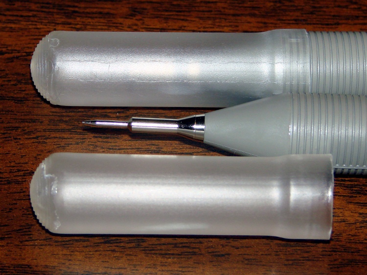
But then I realized the tubes were thermoplastic, held each one over a stove burner until the open end went transparent and droopy, rammed it down over the probe tip, and trimmed off the ragged edge. Worked fine, fits securely, and even looks pretty good:
RSR Covers – detail
I’ll never print the adapters, but maybe one of us will tweak the model to do something else…
The OpenSCAD source code:
// RSR Logic Probe / Pulser Cap
// Ed Nisley KE4ZNU December 2012

// Adapts cigar tube to probe body

// Layout options

Layout = "Build";
                    // Overall layout: Show Build
			// Parts: Probe

//- Extrusion parameters must match reality!
//  Print with +1 shells and 3 solid layers

ThreadThick = 0.25;
ThreadWidth = 2.0 * ThreadThick;

HoleWindage = 0.2;

function IntegerMultiple(Size,Unit) = Unit * ceil(Size / Unit);

Protrusion = 0.1;           // make holes end cleanly

//----------------------
// Dimensions

ProbeDia = 18.0;				// dia of main body
ProbeTipDia = 6.8;				// dia at end of plastic cone
ProbeTipLen = 30.0;				// length of metal ferrule + tip
ProbeConeLen = 17.5;			// cone taper length

TubeOD = 17.25;
TubeWall = 0.50;
TubeID = TubeOD - 2*TubeWall;

TubeLen = 15;					// slip fit over tube body

BodyLen = 20;					// slip fit over probe body

WallThick = 3.5*ThreadWidth;		// basic adapter wall thickness

AdapterLen = TubeLen + BodyLen;
AdapterOD = ProbeDia + 2*WallThick;
AdapterSides = 4*4;

//----------------------
// Useful routines

module PolyCyl(Dia,Height,ForceSides=0) {           // based on nophead's polyholes

Sides = (ForceSides != 0) ? ForceSides : (ceil(Dia) + 2);

FixDia = Dia / cos(180/Sides);

cylinder(r=(FixDia + HoleWindage)/2,
         h=Height,
         $fn=Sides);
}

module ShowPegGrid(Space = 10.0,Size = 1.0) {

    Range = floor(50 / Space);

    for (x=[-Range:Range])
        for (y=[-Range:Range])
            translate([x*Space,y*Space,Size/2])
            %cube(Size,center=true);

}

module Probe() {
	union() {
		cylinder(r=((ProbeDia + HoleWindage)/2),
				 h=(BodyLen + 1.2*Protrusion),$fn=2*AdapterSides);
		translate([0,0,(BodyLen + Protrusion)])
			cylinder(r1=(ProbeDia + HoleWindage)/2,
					 r2=ProbeTipDia/2,
					 h=ProbeConeLen,$fn=2*AdapterSides);
		cylinder(r=ProbeTipDia/2,h=(BodyLen + ProbeConeLen + ProbeTipLen),$fn=2*AdapterSides);
	}
}

module ProbeSleeve() {

	difference() {
		cylinder(r=AdapterOD/2,h=AdapterLen);
		translate([0,0,-Protrusion])
			Probe();
		PolyCyl((TubeOD + HoleWindage),(AdapterLen + Protrusion),2*AdapterSides);
	}
}

//----------------------
// Build it!

ShowPegGrid();

if (Layout == "Show")
    ProbeSleeve();

if (Layout == "Build")
    translate([0,0,AdapterLen])
		rotate([180,0,0])
			ProbeSleeve();

if (Layout == "Probe")
	Probe();
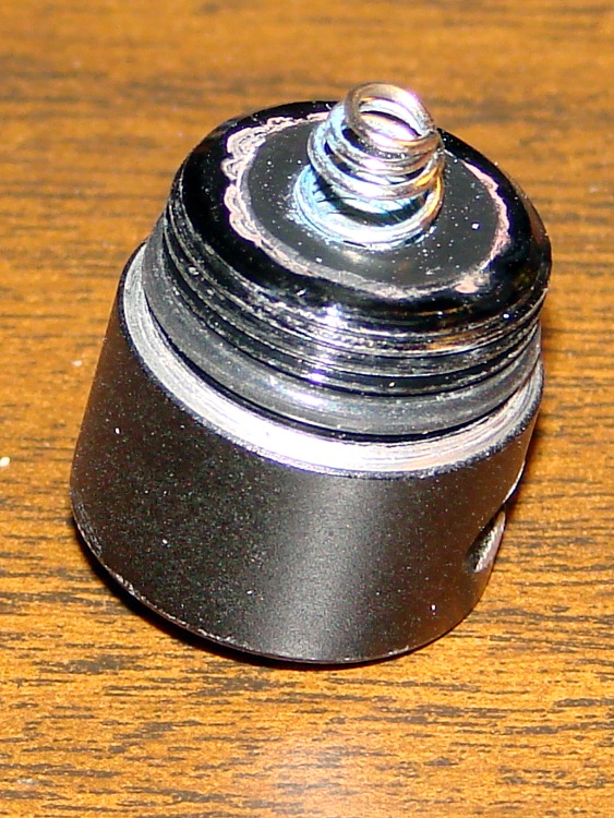
The pushbutton switch on the end cap of a cheap LED flashlight became intermittent, for reasons that should be obvious:
LED Flashlight switch – intact
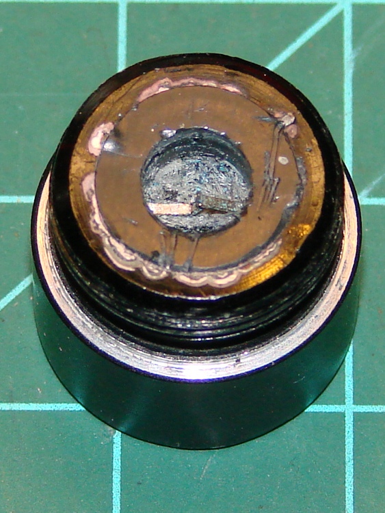
Pulling the spring contact out revealed the usual situation inside:
LED Flashlight switch – spring removed
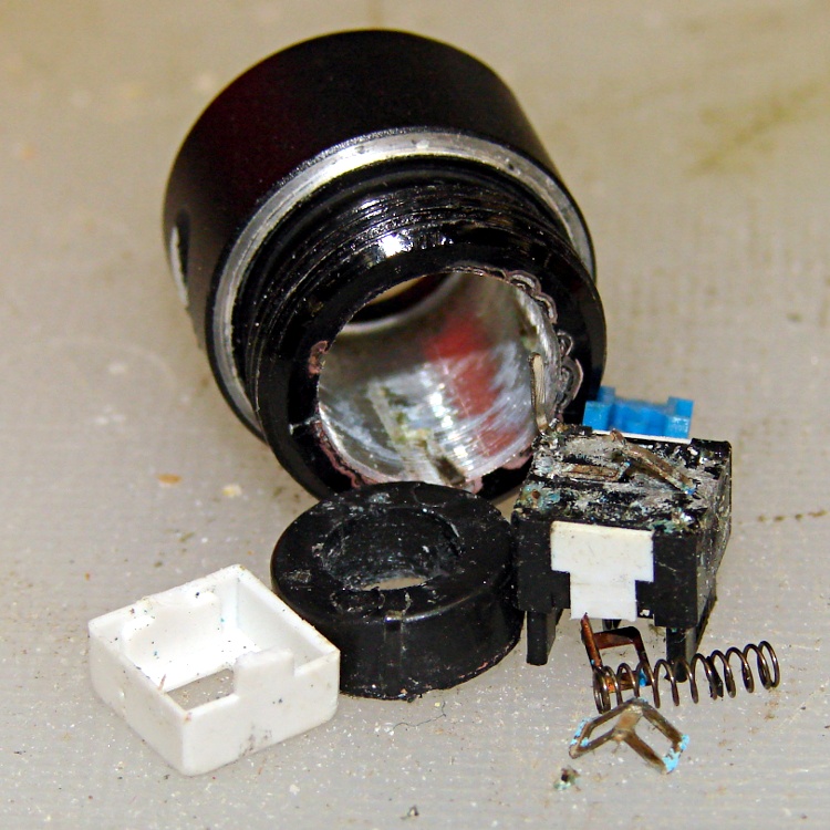
I thought that the discolorations around the central plug indicated a solder joint between the two, but the scratches showed that the plug was actually a press-fit plastic cylinder. Having nothing to lose, I pried the rubber dome off the outside of the switch, balanced the cap’s outer rim on the bench vise, centered an aluminum cylinder over the switch post, and gave it a hammer shot:
LED Flashlight switch – guts
It appears the Basement Warehouse Wing inventory lacks a push-on switch that fits the cap, so this one goes on the pile of potentially useful parts. If a suitable switch appears, I know what to do with it, but if I should need a nice aluminum cylinder that fits a trio of AA cells before then, well …
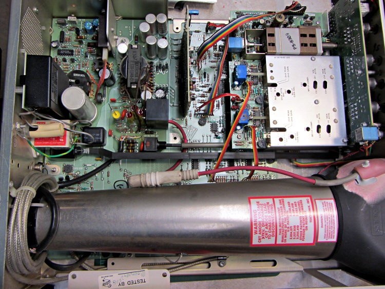
My trusty Tek 2215A oscilloscope might be useful for a Larval Engineer engaged in late-night debugging away from the lab, but the power switch has become flaky: sometimes the ‘scope didn’t turn on at all, sometimes the switch required multiple pokes, sometimes everything worked fine. Removing the cover revealed there’s a long plastic bar connecting the power button on the front panel (to the right in the picture) to the power switch near the rear panel AC line socket, tucked under the EMI filter with the red sticker:
Tek2215A – internal top view
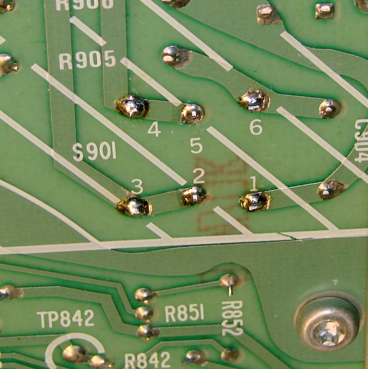
Removing the high voltage shield below the PCB reveals the switch has DPDT terminals, but it’s wired as DPST:
Tek2215A power switch – PCB terminals
This knowledge will come in handy later…
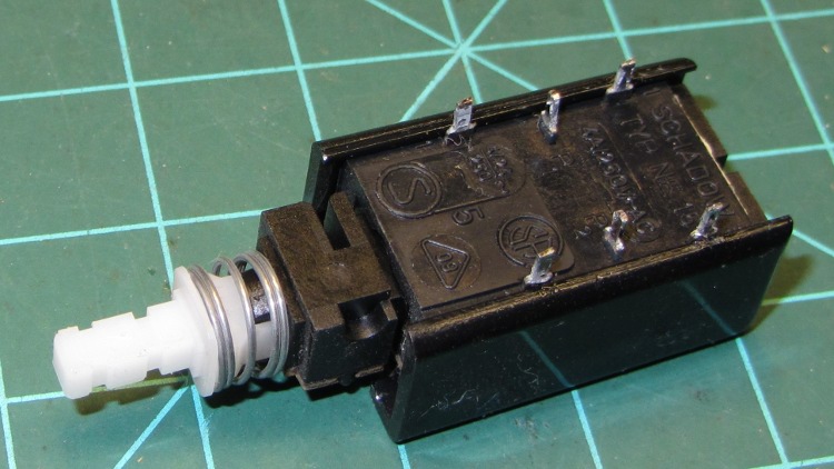
Unsoldering the switch and wriggling the bar out of the front panel puts the switch on the bench, solder terminals upward. A plastic shell snapped around the actual switch insulates the top of the six terminals from prying fingers:
Tek2215A power switch – bottom
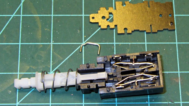
Remove the shell, remove the toggle-action U-shaped steel pin, release the spring, and pull off the top plate:
Tek2215A power switch – internal
Remove the plunger hardware, remove the rocker arms and their springs:
Tek2215A power switch – disassembled
One contact on each rocker shows signs of distress, but the other button remains pristine (having never seen any voltage differential):
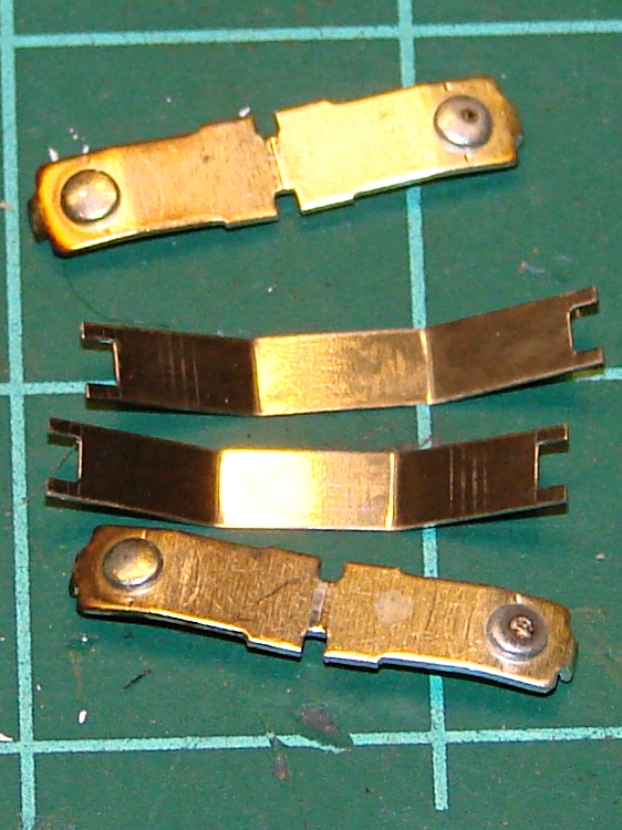
Tek2215A power switch – rockers
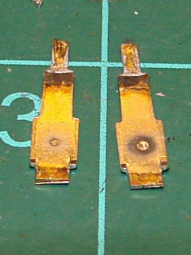
Pull out the fixed contact tabs and note that they’ve been scorched a bit. The one on the right corresponds to the bottom rocker above:
Tek2215A power switch – contact tabs
I cleaned everything with a fiber wipe wetted in DeoxIT, then decided that I’d take the easy way out. The tabs have heavy silver plate on both sides, so I flipped them over and reinstalled them with the unused side facing the rockers. The rockers went back in with their unused contact buttons facing the flipped tabs, so we now have fresh, shiny new contact surfaces. Reassemble the switch, soldered it in place, button up the case, and a firm push on the button lights the ‘scope exactly the way it should.
While I had the cover off, I measured the ESR of all those electrolytic capacitors: they’re in fine shape!
The next time the switch needs repair, in another couple of decades, someone can swap in the completely unused tabs from the other end of the switch, then pick whichever contact buttons look best… [grin]
A trio of 5 mW laser modules arrived with a bunch of other surplus gear after an end-of-year sale:
5 mW Laser Module
It runs on 5 V at 20 mA, determined by the 91 Ω SMD resistor soldered across the terminals at the back of the PCB. That suggests the laser diode itself runs at about 3.2 V: 5 V – 0.020 A * 91 Ω.
The brass case connects to the red (positive) wire, so you must insulate the laser module from the usual grounded metal chassis.
Two of the three lasers arrived badly defocused, but a twist of the brass barrel broke the sealing glue and a bit more twiddling found the sweet spot.
Running one of these from an Arduino would be just like the UV LED: redefine a bit in the shift register bitfield and drive the laser with a MOSFET switch.
I’d be tempted to bypass the SMD resistor and run it from an LM317-style current regulator hitched directly to the raw battery; I’m pretty sure I have some LM317 regulators in TO-92 packages. The sense resistor would be 62.5 Ω = 1.25 V / 0.02 A, dissipating 25 mW = 1.25 V * 20 mA. From a freshly charged 7.2 V Li-ion battery at 8.5 V, the regulator would dissipate something like 80 mW =(8.5 – 1.25 – 3.2 V) * 20 mA.
Or just add more series resistance and ignore the brightness variation?
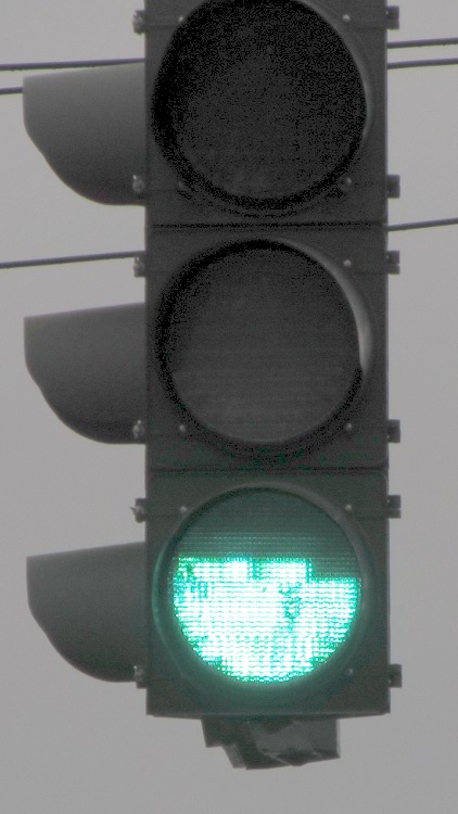
In our (admittedly limited) travels around New York State during the last half decade or so, I’ve seen many (as in, dozens of) traffic signals with this failure:
Apparently the topmost LED string burns out first, leaving the other two (?) strings intact. The earliest picture I have dates back to 2008, so this is a problem of long standing that’s probably wiped out any projected maintenance cost reduction for the entire purchase. The most recent failure I spotted, a few weeks after taking this picture, has a flickering upper string that means it’s not long for this world.
Somewhere up around Albany, I recently saw a green signal with only that string lit up and the other two (?) strings dead, but that’s the sole exception to the pattern.
Of late, NYS DOT has been installing a different green lamp with the LEDs in each string scattered over the entire surface and no diffuser. That means a failed string, of which I’ve already seen several examples in the area, darkens a few spots without being particularly obvious; a less common failure has a few flickering “pixels” that will eventually go dark. While that’s a net win, I wonder why only green lamps have this problem: we very rarely see red or amber lamps with any failed LEDs.
One red LED lamp down the road did fail spectacularly: the whole thing flashed, slowly and somewhat irregularly. Not a flicker, but a flash: long off and short on.
It’s hard to get pictures of failed traffic signals…
While I suppose I should report them, previous attempts to do so have only led to requests for the ID number of the traffic control box, which generally can’t be seen from the traffic lane. I am not stopping at an intersection, getting out, finding the box (perhaps crossing the intersection to get there), finding the ID number, and taking a picture for later reference; you know what happens to people who take pictures of infrastructure. You’d think the signals could phone home on their own, but they’re likely not connected.