
The default MPCNC configuration wires the two stepper motors on each axis in series, doubling the total resistance and inductance of a single motor. The stock Automation Technology motor presents 2.8 Ω and 4.8 mH in each winding to the driver, for an L/R time constant of τ = 1.7 ms. Doubling both doesn’t change the ratio, but including the harness wiring resistance gives 1.6 ms = 9.6 mH / 6 Ω.
The default DRV8825 driver configuration uses 1:32 microstepping, which I thought was excessive. I replaced the stock RAMPS setup with a Protoneer / GRBL setup using A4988 drivers in 1:16 microstepping mode, got it configured, and made a few measurements:
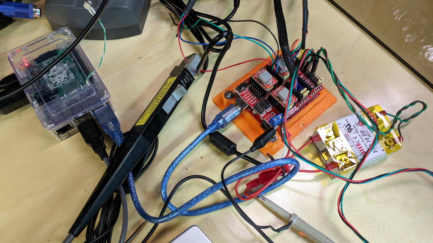
The current probe measures the winding current in the red wire. The voltage probe at the bottom isn’t doing anything, because I ran out of hands.
Here’s a 10 mm X axis move at 3600 mm/min = 60 mm/s:

The top trace shows the winding current at 500 mA/div. The bottom trace shows the voltage applied to the winding at the A4988 driver pin.
Basically, the +12 V supply doesn’t provide enough headroom to let the driver force the required current into the winding at full speed, which is why the peak current decreases as the step rate increases and the sinusoid becomes a square(-ish) wave. The applied voltage switches rapidly to maintain the proper winding current when the axis is stationary or moving slowly (where the driver’s PWM current control works fine), but turns into a square (well, rectangular) wave as the pace picks up (and the driver loses control of the current).
The motor drives a 16 tooth pulley with a 2 mm belt pitch, so each revolution moves 32 mm of belt. With 1:16 microstepping, each revolution requires 3200 = 200 full step × 16 microstep/step pulses, which works out to 100 step/mm = (3200 step/rev) / (32 mm/rev). At the commanded speed near the middle of the trace, the driver must produce 6000 step/s = 60 mm/s × 100 step/mm, so each step lasts 167 μs, about τ/10.
In round numbers, the first full cycle on the left has a 20 ms period. Each full cycle = 4 full steps = 64 microsteps, so the belt moved (60 step) / (100 step/mm) = 0.6 mm, at an (average) speed of 30 mm/s = 1800 mm/min. The current begins to fall off by the third cycle with a 12 ms period, a pace of 50 mm/s = 3000 mm/s, and pretty much falls off a cliff by 60 mm/s in the middle.
To be fair, those are aggressive speeds for milling, but lasers and 3D printers tick along pretty quickly, so they’re not unreasonable.
More study is indicated, as the saying goes …
