The Smell of Molten Projects in the Morning

Ed Nisley's Blog: Shop notes, electronics, firmware, machinery, 3D printing, laser cuttery, and curiosities. Contents: 100% human thinking, 0% AI slop.

Month: May 2013

  • Belkin F6C1500 UPS Battery Wiring Arrangement

    Given the length of the battery wires inside a Belkin F6C1500 UPS, you might think any arrangement will work. Not so. The wires from the guts of the UPS must exit to the batteries exactly like this:

    F6C1500 Battery wires from UPS
    F6C1500 Battery wires from UPS

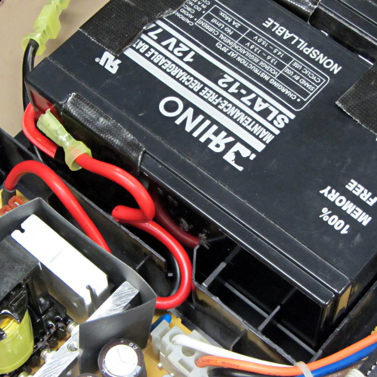
    There’s a black wire tucked under the red wire, both of which must exit though the angled slot and run toward the front of the battery compartment.

    Seen from the front, the red wire connects the positive terminal of the lower (left) battery to the negative terminal of the top (right) battery and the black wire connects the negative terminal of the lower battery to the UPS circuitry:

    F6C1500 Battery interconnect wires
    F6C1500 Battery interconnect wires

    Trust me on this: there is no other arrangement of those wires that will simultaneously connect everything properly and fit within the case.

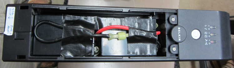
    As for disassembly, the small tab on the left end of the case holds the front panel in place. Press that inward with a flat screwdriver, then slide the cover toward the tab. Four locking slots along the sides will disengage and you can then lift the panel off.

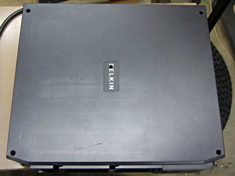
    With that out of the way, there’s a screw hidden under the BELKIN label in the middle of the removable cover:

    Belkin F6C1500 UPS Cover Screw Locations
    Belkin F6C1500 UPS Cover Screw Locations
  • PLA vs. Methylene Chloride: Joint Peel Strength

    The only commonly available PLA adhesive seems to be methylene chloride, which is common only because it’s part of really nasty paint stripper that actually works; I suspect you can’t buy the pure stuff anywhere.

    Anyhow, I picked a pair of flat line width test plates from the PLA scrap pile, dabbed paint stripper on each, and clamped them together overnight:

    PLA test coupon - clamping
    PLA test coupon – clamping

    Unlike acetone on ABS, paint stripper doesn’t actually combine the parts into a single fused unit; I could peel the two plates apart with some effort:

    PLA test coupon - paint stripper adhesion
    PLA test coupon – paint stripper adhesion

    That picture shows the results of two glue-and-peel tests, with much the same result along the top and bottom edges. Some solvent damage appears as a thin white line around the edge of the glued joint, but with some care that wouldn’t be too bad.

    I think paint stripper makes an acceptable adhesive for PLA, at least for joints that aren’t subject to peeling loads. You must design an interlocking mechanical joint, perhaps filled with epoxy, to withstand peeling loads, which isn’t nearly as good as the ABS option of just fusing the parts together.

  • Makergear M2: Radial Engine Cylinder Head

    After some chiding by Jetguy, here’s a cylinder head from the MBI radial engine:

    Radial engine cylinder head - top - plug oblique
    Radial engine cylinder head – top – plug oblique

    The side fins came out nicely, but the top fins had a few misplaced threads (far side to the left of the valve):

    Radial engine cylinder head - intake
    Radial engine cylinder head – intake

    The view from the other port:

    Radial engine cylinder head - exhaust
    Radial engine cylinder head – exhaust

    Seen directly from the spark plug side, you can barely make out the impossibly thin fin section arching over the plug hole:

    Radial engine cylinder head - plug side
    Radial engine cylinder head – plug side

    The cylinder side looks OK:

    Radial engine cylinder head - bottom
    Radial engine cylinder head – bottom

    I built it standing on one of the ports with the fins vertical, as shown above, which is probably the only way to do it without soluble support material. If I were doing it for real with non-soluble support, I’d be tempted build it flat on the cylinder side with support under the piston head and thin support blocks inside the side fins. It’d look about the same, but with better finish on the top fins.

    All in all, I’d say it looks pretty good.

    The Slic3r header:

    ; generated by Slic3r 0.9.10-dev on 2013-04-20 at 20:24:18
    
    ; layer_height = 0.20
    ; perimeters = 1
    ; top_solid_layers = 3
    ; bottom_solid_layers = 3
    ; fill_density = 0.1
    ; perimeter_speed = 60
    ; infill_speed = 80
    ; travel_speed = 200
    ; nozzle_diameter = 0.35
    ; filament_diameter = 1.73
    ; extrusion_multiplier = 0.9
    ; perimeters extrusion width = 0.52mm
    ; infill extrusion width = 0.52mm
    ; solid infill extrusion width = 0.52mm
    ; top infill extrusion width = 0.52mm
    

    The STL file came direct from Thingiverse, riddled with the reversed normals and holes common to solid models generated by Sketchup, but a pass through NetFabb’s cleanup made it printable. The original STL positioned it far, far out on the X axis, so if you don’t see it right away, rummage around a bit.

  • Monthly Science: Larval Engineer

    Part of becoming an engineer involves discovering the difference between what works and what doesn’t, with the goal of doing more of the former and less of the latter. In tech fields, gaining such knowledge requires observations, records, and graphs.

    Our Larval Engineer is off to a good start, having collected her projects & notes into blog format.

    The alert reader may recognize the understated presence of a guiding hand, here and there, in some projects. I needed one, too, back in the day, even if I didn’t appreciate it (by at least the same amount). Fortunately, blogs hadn’t been invented, so you’ll never know.

    Karen at the lathe
    Karen at the lathe

    You may enjoy her story of the Taxi Horn project, which you see here in the lathe.

    Memo to Self: After launch, guiding hands must remain with the gantry. One must Just. Let. Go.