Ed Nisley's Blog: Shop notes, electronics, firmware, machinery, 3D printing, laser cuttery, and curiosities. Contents: 100% human thinking, 0% AI slop.
So I measured the thickness of the black acrylic sheet I’m using for the Totally Featureless clock and machined the rabbets to match. Went to assemble everything and the rabbets are too shallow!
Come to find out that the sheet varies in thickness from about 0.437 to 0.475 across the four pieces I’d cut and, of course, I’d measured the thinnest end of the thinnest piece. Makes no sense to me, as I’d expect the thickness to be pretty well controlled over a few feet of sheet, but that’s not how things went down.
The simplest solution was to mill a flat on the inside of the case to match the rabbet, so all four panel ends were the same thickness. The sketch below has the straight dope.
Acrylic sheet thickness fix
Milling with a 3/8-inch end mill at 2500 rpm, 10 ipm, in one pass with no cooling was OK.
I’ll insert some brass shimstock into the rabbets to make the outside edges wind up flush.
This is pretty much the same general idea and setup as the one I described there, but with the panel flat against the tooling plate.
Milling rabbet on top panel
The cutter sits at the far right end of its maximum travel. I made the rabbet in three manual CNC passes.
To set up for the rest of the cut:
G0 X-4.25 to clear the left end of the panel
Loosen the three clamps, slide the panel leftward
Push the panel against the brass tubes
Tighten the clamps
And away we go…
Complete rabbet
One disadvantage: you can’t do a final finishing pass along the entire length of the cut. There are tool marks at the stopping point, but nothing really objectionable on the back of a clock where a panel will cover the rather ugly guts.
The brass tube “locating pins” work surprisingly well.
About 2000 rpm with 3/8 inch end mill. Cut 1/8 inch wide and 0.25 inch deep @ 10 ipm in three passes. Finish pass 15 ipm at 0.257 deep to make it pretty.
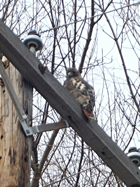
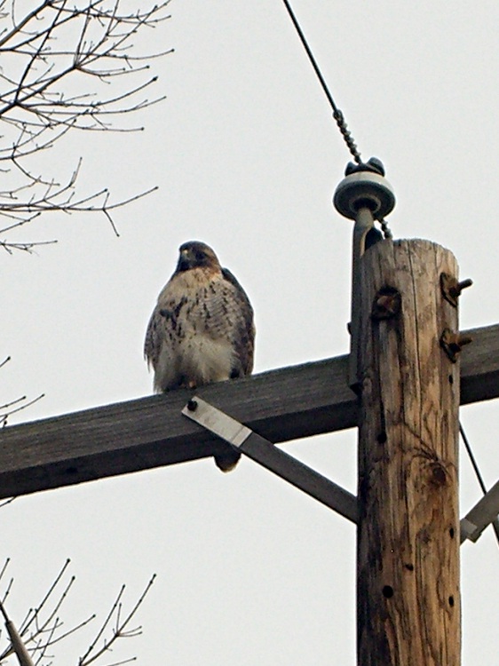
It was quite cold (notice his fluffy down coat) and he was content to watch us go by. In fact, it was so cold the crows were just flying by without doing their usual hawk harassment.
Taken with a Casio ZX-850 pocket camera: no fancy optics. Looks it, too… these are tight crops from much larger images. Click for bigger, but not wonderfully detailed, images.
Having flycut the acrylic panels to the proper width, I had to cut them to the proper length, too. This picture shows the lashup I used to hold them down during the operation…
Clock top panel fixture
The brown bar sticking out to the left is one of the bookshelf struts that held the toolmaker’s vises down during the flycutting; it’s now secured to the Sherline table with a T-nut. A vise clamped to the bar serves as an end stop for the panels.
Brass tubing locating posts
A pair of brass tubes around studs serve as locating pins. To get the things lined up:
Loosely clamp a panel down atop a spacing plate
Push it back against the loose tubes: crudely parallel to X axis
Snug the clamps
Align the panel to the X axis using the laser
Push the tubes against the panel
Tighten their nuts
Top panel end trimming detail
Crude, but good enough for this purpose.
Then a bit of manual CNC to shave off the end. Half-inch mill, 1500 rpm, 150 mm/min, more-or-less 0.5 mm cuts. The panels don’t have to be any exact length, as long as the clock circuit boards fit inside, but the ends must be perpendicular and smooth for good gluing.
The exact part will come when I rabbet the side panels…
The side panel setup was much simpler: same brass posts, same spacer, no need for the long bar hanging off to the left.
The Totally Featureless Clock will have a black acrylic case with a Graylite Lexan faceplate. The top & bottom panels are 11.75 inches long, which is much too large for the Sherline’s 9-inch maximum X travel.
Fortunately, in this case I can cheat.
This setup cut the panels to the proper width. A pair of parallel blocks, made from some mysterious glass-like material and ground very nicely flat, support the panel just over the body of the four toolmaker’s vises lined up along the tooling plate. I drilled the brown bookshelf rails to match the tooling plate and secured them with 10-32 studs.
The front rail secures the vise bodies to the tooling plate; they’re aligned parallel to the X axis by the simple expedient of laying a parallel along the back edge and matching that to the tooling plate. No real precision is in order here; the flycut is across the whole top edge.
The rear rail holds the movable vise jaws down; they tend to rise up just slightly when tightened, but the difference amounts to barely enough to release pressure on the parallel blocks. Not enough to matter, as it turned out.
The general notion is to flycut about 2/3 of the length of the panel, then slide it far enough to cut the remainder. Flip it over and flycut the other side the same way.
About 1000 rpm and 150 mm /min, cutting 0.5 mm or so on each pass.
This worked surprisingly well. I expected to find a bow in the middle due to an uneven bandsaw cut on the initial downward side, but it was all good; evidently the blocks were wide enough to average things out.
The joint where the two cuts meet turns out to be visible, but barely detectable with a fingernail: entirely suitable for this application. I’ll hit the sides with sandpaper on a sheet of plate glass before bonding them to the faceplate.
Flycutting the end panels was much simpler: one pass clears their entire length. I moved the clamping rails to simplify the whole process; turned out that clamping the movable jaw didn’t really gain very much at all while complexicating the slide-the-stock process beyond belief.
Flycutting end panels
Overall, the width varies by about two mils along the length of the long panels and they’re perfectly straight as measured against a surface plate. Definitely close enough!
Discovered that one of my toolmaker’s vises had a defunct screw securing the jaw to the body: one side of the head simply vanished over the years. Hadn’t mattered up until now, but I really wanted the jaw to not ride up when clamping the workpiece and the screw was rather loose.
It’s difficult to tighten a screw with half a slot…
Eventually I figured out that the screw has a 6-40 thread. My Brownells Gunsmith screw assortment (which they no longer offer) has, among others, 6-48 and 8-40 screws in flat, fillister, socket, and round head, but nothing in 6-40.
After exhausting all other possibilities, I looked in the assortment box again and found four round-head crosspoint screws with captive lockwashers that I must have salvaged from some dead piece of gear.
Of course, they turned out to be 6-40. Whew!
Chopped off the lockwasher, added a dab of Loctite, and it fit perfectly. I flipped the sliding plate over, as it appeared somewhat worn, but I’m certain that didn’t make any difference.
The screw must have a flat head (and you can’t flip the plate over) if you mount the vise on a machined V-way, but that’s not anything I’m likely to do. In that event, maybe I’ll just file the top off the screw and be done with it.
My Microsoft Comfort Curve 2000 keyboard has the usual gaggle of multimedia & program-control keys. I tend to not use many of those keys, but Volume +/- and Mute come in handy.
The default Arch Linux keyboard configuration, whatever it is, reports the appropriate codes from the keyboard, so I didn’t have to fiddle with any of that.
I used the same basic procedure as I described there, with tweaks to the amixer commands: