Ed Nisley's Blog: Shop notes, electronics, firmware, machinery, 3D printing, laser cuttery, and curiosities. Contents: 100% human thinking, 0% AI slop.
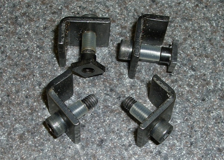
A small improvement: add a snippet of heat stink shrink tubing to the screw in the L-shaped hold-down clamps and the screw won’t go walkabout in your tooling widget case.
Make it the same length as the distance from the clamp to the surface and it’ll remind you how far to screw on the T-nut when you swap the clamps from tooling plate to milling machine table.
Sherline clamp screws with heatshrink
Sherline clamp in action
The Sherline Mill Vise (PN 3551) comes with a set of clamps. They’re also available separately as the 4-Jaw Hold-Down Set (PN 3058).
Quite often, the values you need for voltage regulators, like the venerable LM317 and its ilk, don’t work out to anything you have in your parts bin. What to do?
One of the really nice things about SMD resistors is that you can stack them up without much effort. That parallels their value, so you can only make the final value smaller than any of the stacked resistors, but we can work with that.
The schematic shows part of a multi-voltage power supply for the EPROM programmer I mentioned there. Normally you use a 240-Ω resistor between the Output and Adjust terminals, but anything in that range will work fine. Alas, when I went to the parts bin, that’s the value I didn’t have any of.
But, having recently acquired an assortment of 60-some-odd 1% chip resistors, 100 to the bag, I had enough raw material to make it work. In fact, the values in the schematic reflect the parts on hand, which is how it sometimes happens.
A pair of 499-Ω resistors in parallel gives you 249.5 Ω, close enough to 240 (and shown as 250 because that’s only 0.2% off). Plug that value and the desired voltages into the LM317 equation to find the other resistors:
12.5 V = 1.25 * (1 + R / 250)
R = 250 * ((12.5 / 1.25) – 1) = 2250 Ω
If you happen to have something close to that in your parts heap, great. I didn’t, and a stock 2200 Ω 5% resistor would produce 12.25 V; a bit lower than I wanted.
Three sets of stacked chip resistors
This pic shows the solution: stack some SMD resistors to get the right value.
To make this work easily, you need a calculator that has a reciprocal (1/x or x-1) key. My ancient HP-48 does that, natch, but both of the Official School Calculators our daughter uses has 1/x as a shifted function. Your mileage will certainly vary.
Anyhow, the reciprocal of the resistance of two parallel resistors, RA and RB, is the sum of their reciprocals. Got that?
1/R = 1/RA + 1/RB
If you know the total resistance R that you want and one of the resistors RA, then you find the other resistor RB thusly:
1/RB = 1/R – 1/RA
In order to get 2250 Ω, I started with the next higher value in the assortment, 2740 Ω, and turned the crank:
1/RB = 1/2250 – 1/2740 = 79.4809E-6
RB = 1/79.4809E-6 = 12.58 kΩ
As it happens, the assortment didn’t have that value, either, but it did have 15 kΩ. The parallel resistance of 2740 and 15 k is:
2317 = 1 / (1/2740 + 1/15000)
So turn the crank one more time to find the third resistor RC:
1/RC = 1/2250 – 1/2317 = 12.814E-6
RC = 78.04 kΩ
Well, that isn’t one of the values I have either, but I do have 82.5 kΩ. The parallel value of those three resistors is:
1/R = 1/2740 + 1/15000 + 1/82500 = 443.75E-6
R = 2254 Ω
Which is 0.1% off the desired value. Close enough.
Actually, it won’t be nearly that close, because the 2740 Ω resistor can be off by 27 Ω either way. If you really care, measure the actual values and feed those into the equations. If, of course, you can measure resistors better than 1% and you don’t care about temperature effects and suchlike.
This is appropriate for one-off projects and prototypes, not production runs, but it’s a handy trick to keep in mind. If you want to be fancy, you can lay the circuit board out with parallel resistor tracks and make it look like you knew what you were doing all along…
The instructions for our Weber gas grill would have us lavish more care on it than we do on our car, which isn’t actually saying much. Nonetheless, once a year I gotta clean the crud out, whether it needs it or not, because not even I believe heat kills that stuff.
Used to be, that was a thoroughly disgusting job of hand-scraping carbonized gunk and scrubbing gooey muck in cramped quarters. Having acquired a pressure washer, cleaning the grill is almost enough fun that I might do it more often. It even gets the mildew (or whatever that schmutz might be) off the wood handles & platforms, which I would have bet was impossible.
Pressure washer side effects
However, if you’re even a teensy bit fussier than we are about the looks of your castle, you might want to not lay the grates & “flavorizer bars” on the driveway to blast ’em clean. Turns out that the overspray strips the grunge right out of the top layer of asphalt, leaving a white trail behind.
As I mentioned there, we have white LED bike headlights clamped to the amateur radio antennas on our bikes, facing rearward to eliminate the “But, Officer, I didn’t see him” line from the accident investigation. That works fine during daylight hours, but it’s rather blinding after dark and, in any event, taillights are supposed to be red (after 1 Nov 2009, they may also be amber).
The easiest way to get that result, without having to tote along Yet Another Light, is to slip a red filter over the white LED lens. This dramatically reduces the light output, because the yellow phosphor used to get white light out of what’s basically a blue LED doesn’t emit much energy in the red end of the spectrum, but it’s plenty good enough to be seen from the requisite 300 feet.
Amber filters would be a much, much better match to the phosphor and I’ll use them next year when they’re legal.
For what it’s worth, we’ve discovered that the more we look like UFOs after dark, the more clearance we get. The bikes are extensively reflectorized and lighted, plus we have reflective arm and leg bands. If somebody hits us, it’s because they did it intentionally; that’s usually the story with drunks and punks, alas.
Red filter components
I cut two transparent disks from ordinary electronics packaging material, plus a red disk from the Primary Red filter material mentioned there, stacked them on the headlight, and fired some big heat stink shrink tubing around them. The tubing extended maybe 3 mm past the end of the headlight and shrank into a neat lip that matched the bezel around the lens.
The tool to have for this sort of job is an Olfa Compass Circle Cutter. It leaves a pin prick in the center of the circle, but if you’re gentle that won’t be a problem in this application.
The shrunken tubing will be exceedingly difficult to pull off the headlight, so you may want to wrap a layer of tape around the bezel before shrinking. Peel the tape off when you’re done and the tubing will have a few mils more clearance.
No adhesive on earth will stick to both the polypropylene disks and the heatshrink tubing, but you can try silicone snot if you want. I made the disks just slightly larger than the bezel so that the tubing captures them as it shrinks. These things spend much of their lives in a ziplock baggie, so durability isn’t an issue.
Red filter installed
In any event, the filter looks like this when it’s installed. Because of the odd way I mounted the headlights, the side lenses aren’t visible (and they’re white, not red), but we have plenty of other light visible from the side.
For the straight dope on current NYS bicycle laws, go there, click on the “Laws of New York” link, search for “bicycle”, then click on section 1236. It’s New York’s idea of a useful Web interface: get over it.
The bezels on our lights are beginning to crack, so it’s probably time to start thinking about a killer street-legal day/night amber taillight. High intensity LEDs are dirt cheap these days…
I’ve bought plenty of batteries from batteries.com over the years, but the alkaline AA cells I picked up last year have been a real disappointment: some had very short service lives. It took quite a while to figure this out, as I mentioned there, and when I finally got around to checking the rest of the package, most of them were dead… in Spring 2009 with a 12-2012 date code.
One characteristic of the weak / dead cells is that the negative terminal is swollen, even on the deaders direct from the package. This picture shows four cells removed from service: the front two are used with some remaining charge, the rear two are dead.
When I checked the package, most of the dead-on-delivery cells had swollen bottoms, so I suspect they had a manufacturing problem with at least one batch of cells.
A query to batteries.com asking about this got no reply. Perhaps they were busy dealing with the aftermath of their security breach?
A 48-pack of alkaline cells from the late Circuit City, bought about the same time, seems just fine.
Many interesting projects require more digital output bits than the Arduino hardware can support. You then use 74HC595 serial-in/parallel-out chips and that tutorial pretty well explains how it works. The shiftOut() library function squirts a byte out through an arbitrary pin, leading with either the high or low bit.
Software SPI: Clock and Data
Just drop one byte into shiftOut() for each ‘595 lined up on your board. Remember to latch the bits (LOW-to-HIGH on RCK @ pin 12 of the ‘595) and enable the output drivers (LOW on -G @ pin 13, similarly) when you’re done sending everything. You can have separate latches-and-enables for each ‘595 if that suits your needs, although then you once again run out of Arduino bits pretty quickly. It’s entirely possible to devote a ‘595 to latches-and-enables for the rest of the chain, but that gets weird in short order.
The scope shot shows that shiftOut() ticks along at 15 µs per bit (clock in the upper trace, data in the lower trace). For back-of-the-envelope purposes, call it 8 kB/s, which is probably less than you expected. If you have a string of 5 external bytes, as I did on a recent project, that’s only 1600 updates / second. It was part of a memory board reader & EPROM programmer: reading an 8 kB ROM chip requires two shift-register runs (one to set the address & data, one to read in the chip output), so the overall rate was on the order of 10 seconds per pass and much worse for programming. You can optimize the number of bits by not shifting out all the bytes, but that’s the general idea.
Because ‘595 chips are output-only, in order to get 8 bits of data into the Arduino board, add a 74HC166 parallel-in/serial-out chip to the string. Alas, shiftOut() doesn’t know about input bits, so you’re on your own.
Hardware SPI: Clock and Data
If you’re going to have to write some code to get input bits anyway, you may as well use the ATmega168 (and its ilk) hardware SPI as it was intended to be used: for high-speed synchronous serial I/O. This scope shot shows the SPI clock (in the top trace again) ticking along at 1 µs per bit, which is 1/16 the Diecimila’s oscillator frequency. You can pick any power of two between 1/2 and 1/128; I used 1/16 because it’s fast enough to make the rest of the software the limiting factor, while slow enough to not require much attention to layout & so forth.
Start by Reading The Fine Manual section about the ATmega168’s SPI hardware, starting at page 162.
The pin definitions, being lashed to internal hardware, are not optional. Note that SCK is also the standard Arduino LED, which won’t be a problem unless you need a tremendous amount of drive for a zillion ‘595s. I stuck an additional LED on Arduino digital pin 2.
#define PIN_HEARTBEAT     2             // added LED
#define PIN_SCK          13             // SPI clock (also Arduino LED!)
#define PIN_MISO         12             // SPI data input
#define PIN_MOSI         11             // SPI data output
Initial hardware setup goes in the usual setup() function:
pinMode(PIN_SCK,OUTPUT);       // set up for "manual" SPI directions
digitalWrite(PIN_SCK,LOW);
pinMode(PIN_MOSI,OUTPUT);
digitalWrite(PIN_MOSI,LOW);

pinMode(PIN_MISO,INPUT);       // configure inputs
digitalWrite(PIN_MISO,HIGH);

SPCR = B01110001;              // Auto SPI: no int, enable, LSB first, master, + edge, leading, f/16
SPSR = B00000000;              // not double data rate
Basically, the “manual” setup allows you to wiggle the bits by hand with the hardware SPI control disabled.
Arduino Hardware SPI Schematic
Here’s a chunk of the schematic so you can see how the bits rattle around. You’ll surely want to click it to get the details…
I put the data in a structure that matches the shift register layout, with the first byte (Controls) connected to the ATmega’s MOSI pin and the last byte (DataIn) connected to MISO. The SCK pin drives all of the serial clock pins on the ‘595 and ‘166 chips in parallel. Your structure will certainly be different; this was intended to suck data from a Tek 492 Spectrum Analyzer memory board.
typedef struct {      // external hardware shift register layout
 byte Controls;       // assorted control bits
 word Address;        // address value
 byte DataOut;        // output to external devices
 byte DataIn;         // input from external devices
} SHIFTREG;

SHIFTREG Outbound;    // bits to be shifted out
SHIFTREG Inbound;     // bits as shifted back in
The functions that make it happen are straightforward:
void TogglePin(char bitpin) {
 digitalWrite(bitpin,!digitalRead(bitpin));
}
void PulsePin(char bitpin) {
 TogglePin(bitpin);
 TogglePin(bitpin);
}

void EnableSPI(void) {
 SPCR |= 1 << SPE;
}

void DisableSPI(void) {
 SPCR &= ~(1 << SPE);
}

void WaitSPIF(void) {
 while (! (SPSR & (1 << SPIF))) {
//        TogglePin(PIN_HEARTBEAT);       // use these for debugging!
//        TogglePin(PIN_HEARTBEAT);
 continue;
 }
}

byte SendRecSPI(byte Dbyte) {             // send one byte, get another in exchange
 SPDR = Dbyte;
 WaitSPIF();
 return SPDR;                             // SPIF will be cleared
}

void CaptureDataIn(void) {                // does not run the shift register!
 digitalWrite(PIN_ENABLE_SHIFT_DI,LOW);   // allow DI bit capture
 PulsePin(PIN_SCK);                       // latch parallel DI inputs
 digitalWrite(PIN_ENABLE_SHIFT_DI,HIGH);  // allow DI bit shifting
}

void RunShiftRegister(void) {
 EnableSPI();                             // turn on the SPI hardware

 Inbound.DataIn  = SendRecSPI(Outbound.DataIn);
 Inbound.DataOut = SendRecSPI(Outbound.DataOut);

 Inbound.Address  =         SendRecSPI(lowByte(Outbound.Address));
 Inbound.Address |= ((word) SendRecSPI(highByte(Outbound.Address))) << 8;

 Inbound.Controls = SendRecSPI(Outbound.Controls);

 PulsePin(PIN_LATCH_DO);                   // make new shift reg contents visible
 PulsePin(PIN_LATCH_ADDRESS);
 PulsePin(PIN_LATCH_CONTROLS);

 DisableSPI();                             // return to manual control
}
Actually using the thing is also straightforward. Basically, you put the data-to-be-sent in the Outbound variables and call RunShiftRegister(), which drops output bytes into SPDR and yanks incoming bytes out, then stuffing them in the Inbound variables. I have separate latch controls for the Controls, Address, and Data chips, although I don’t use them separately here.
You must wiggle the parallel latch enable line on the 74HC166 chip before shifting to capture the data, as shown in CaptureDataIn(). That chip also requires a separate pulse on its serial clock line to latch the data, which you do manually with the hardware SPI disabled. If you’re paying attention, you’ll wonder if that clock pulse also screws up the data in the rest of the chips: yes, it does. If this is a problem, you must add some external clock-gating circuitry, disable the ‘595s, or pick a different input shift register chip; it wasn’t a problem for what I was doing.
Here’s a function that reads data from a RAM chip on the Tek memory board, so it must write the address and read the RAM chip’s output. The PIN_DISABLE_DO bit controls the output buffers on the ‘595 that drives the RAM’s data pins; they must be disabled to read data back from the RAM. Don’t worry about the other undefined bits & suchlike; just assume everything does what the comments would have you believe.
byte ReadRAM(word Address) {
 digitalWrite(PIN_DISABLE_DO,HIGH);            // turn off data latch output
 digitalWrite(PIN_BUS_READ,HIGH);              // allow RAM read access

 Outbound.Controls |=  CB_BUS_CLKPH2_MASK;     // set up RAM -CS gate
 Outbound.Address = Address;
 Outbound.DataOut = 0x55;                      // should not be visible
 RunShiftRegister();

 digitalWrite(PIN_BUS_N_SYSRAM,LOW);           // activate RAM -CS
 CaptureDataIn();                              // latch RAM data
 digitalWrite(PIN_BUS_N_SYSRAM,HIGH);          //  ... and turn -CS off

 Outbound.Controls &= ~CB_BUS_CLKPH2_MASK;     // disable -CS gate
 RunShiftRegister();                           // tell the board and get data

 return Inbound.DataIn;
}
Hardware SPI – Detail of clock and data timing
Here’s a detailed shot of the outbound bit timing. Notice that the upward clock transitions shift bits into the ‘595 and ‘166 chips, while the SPI output data changes on the downward transitions. You can tweak that to match your hardware if you’re using different shift register chips, by messing with the SPCR settings.
Bottom line: using the ATmega168 hardware SPI provided a factor-of-15 speedup and serial digital input, too.

 Schematic")


